

2.7 Axis movements
2.7.1 Linear interpolation with rapid traverse: G00
G00 is used for fast positioning of the tool, however, not for direct workpiece machining. All axes can be traversed simultaneously-on a straight path. For each axis, the maximum speed (rapid traverse) is defined in machine data. Any programmed feedrates (F word) are not relevant for G00.
Example:
N10 G00 X50 Z100
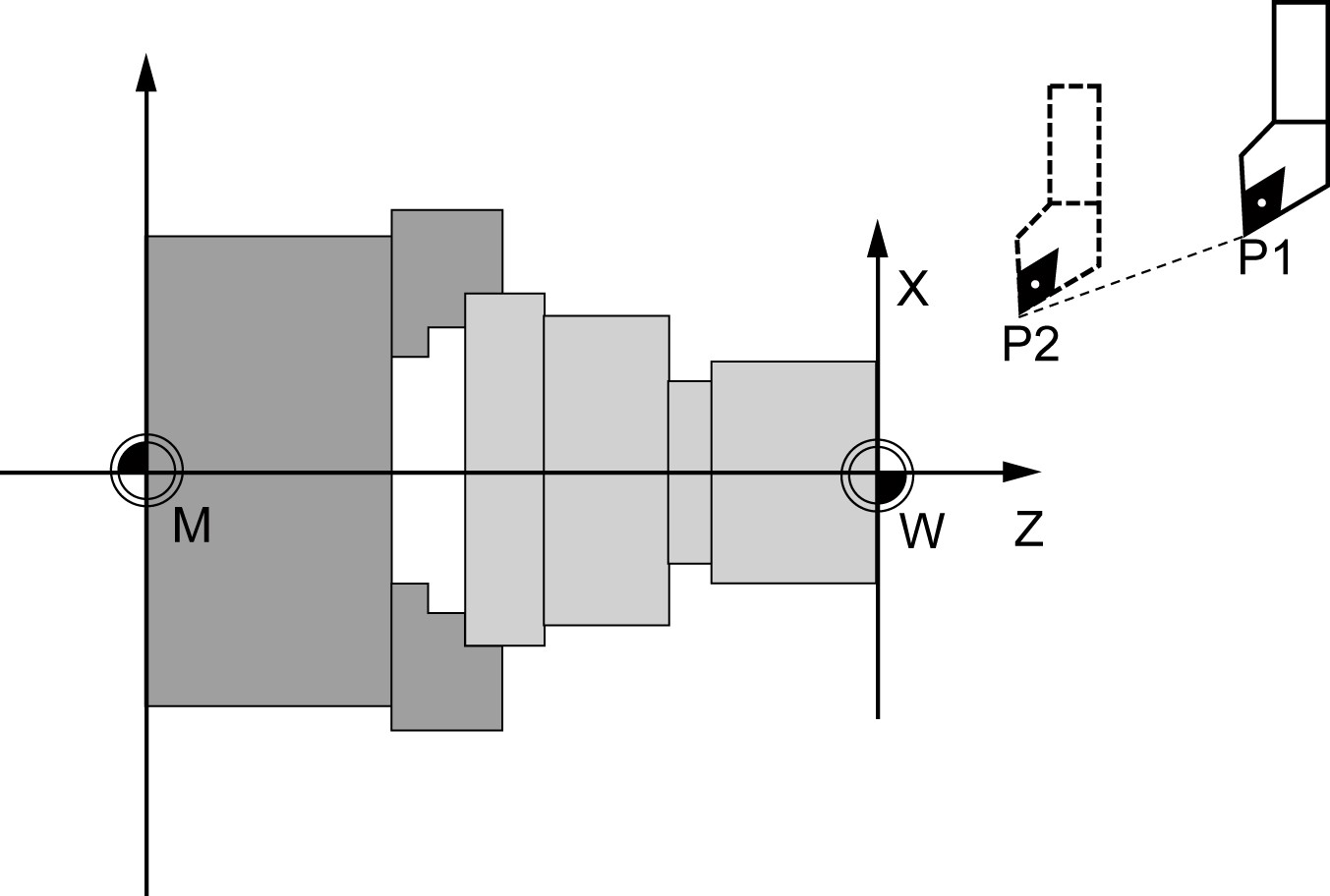
Fig.2.8 Linear interpolation with rapid traverse from point P1 to P2
2.7.2 Linear interpolation with feedrate: G01
The tool moves from the starting point to the end point along a straight path. For the path velocity, is determined by the programmed F word .
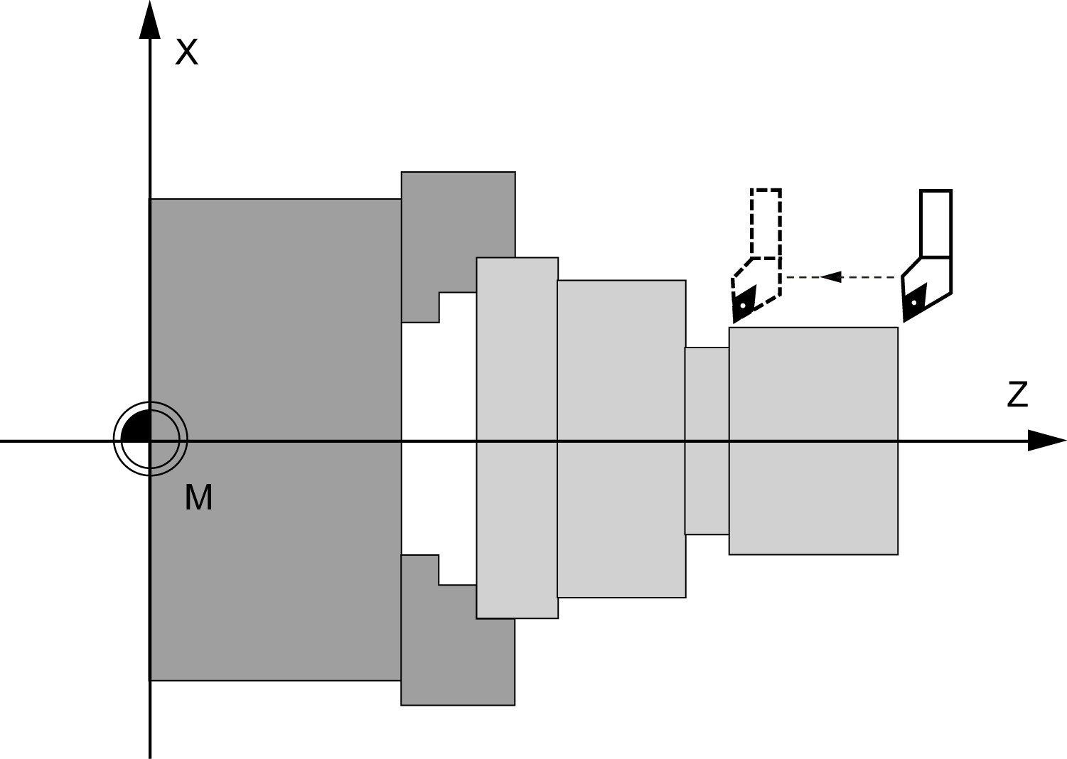
Fig2.9 Linear interpolation with G1
Example:
N10 G54 G00 G90 X40 Z200 S500 M03 ; The tool traverses in rapid traverse,spindle speed = 500 r.p.m., clockwise
N20 G01 G95 Z120 F0.15 ; Linear interpolation with feedrate 0.15mm/r
N30 X45 Z105
N40 Z80
N50 G00 X100 ; Retraction in rapid traverse
N60 M02 ; End of program
An angle can be entered to uniquely define the straight line path if only one end point coordinate of the plane is known for a straight line or for contours across multiple blocks the cumulative end point.

Fig.2.10 Angle value for determination of a straight line
Example:
N10 G94 G01 X2 Z5 F100
N20 G01 X3 ANG=120
OR
N10 G94 G01 X2 Z5 F100
N20 G01 Z2 ANG=120
The angle is always referred to the Z axis. Positive angles are aligned counterclockwise.
Example:
N10 G94 G01 X2 Z5 F100
N20 G01 X3 ANG=120
OR
N10 G94 G01 X2 Z5 F100
N20 G01 Z2 ANG=120
The angle is always referred to the Z axis. Positive angles are aligned counterclockwise.
2.7.3 Circular interpolation: G02/G03
The tool moves from the starting point to the end point along a circular path. The direction is determined by the G function: G02-CW, G03 CCW. For the path velocity, is determined by the programmed F word .
In the system interface of parameter setting, you can set G02/G03 whether a modal instuction by switch. When it is set ‘OFF’, G02/G03 is non-modal instruction; when it is set ‘ON, G02/G03 is modal instruction.
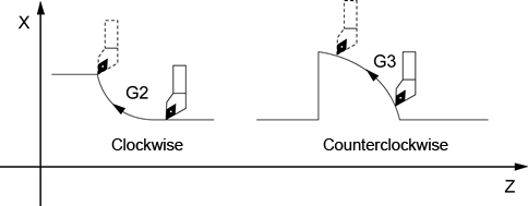
Fig.2.11 Definition of the circular direction of rotation
The description of the desired circle can be given in various ways:

Fig.2.12 Options for circular path programming G02/G03
Example:
1. Definition of center point and end point
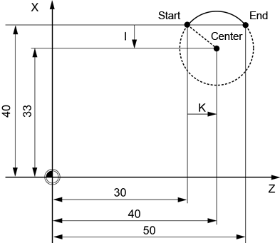
Fig.2.13 Example for center point and end point specification
Center point values refer to the circle starting point!
Example:
DIAMOF
N10 G90 G94 G01 Z30 X40 F100 ; Starting point circle
N20 G02 Z50 X40 K10 I-7 ; End point and center point
2. End point and radius specification
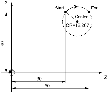
Fig.2.14 Example for end point and radius specification
Example:
DIAMOF
N10 G90 G94 G01 Z30 X40 F100 ; Starting point circle
N20 G02 Z50 X40 CR=12.207 ; End point and radius
With a negative leading sign for the value with CR=-..., a circular segment larger than a semicircle is selected.
3. Definition of end point and aperture angle:

Fig.2.15 Example for end point and aperture angle specification
Example:
DIAMOF
N10 G90 G94 G01 Z30 X40 F100 ; Starting point circle
N20 G02 Z50 X40 AR=105 ; Opening angle and end point
Example:
DIAMOF
N10 G90 G94 G01 Z30 X40 F100 ; Starting point circle
N20 G02 K10 I-7 AR=105 ; Opening angle and end point
Programmable range of AR is 0≤AR<360.
4. The full circle Programming example (only format with center programming):
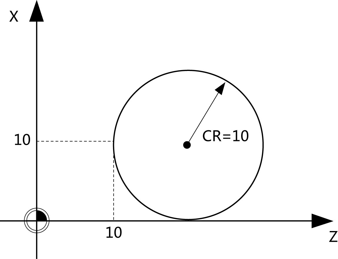
Fig.2.16 Full circle program
DIAMOF
N10 G94 G01 X10 Z10 F100
N20 G03 X10 Z10 I0 K10 F60
2.7.4 Thread cutting with constant lead: G33
This requires a spindle with position measuring system. G33 remains active until canceled by another instruction from this G group...). Feedrate switch does not work while using G33.
The function G33 can be used to machine threads with constant lead of the following type:
1. Thread on cylindrical structures
2. Thread on tapered structures
3. External/Internal thread
4. Multi-block thread (series of threads)
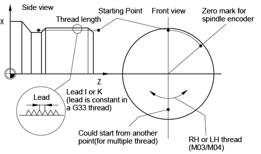
Fig.2.17 Thread cutting parameter
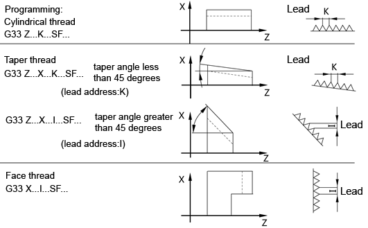
Fig.2.18 Thread cutting type
For tapered threads (2 axis values required), the required lead address I or K of the axis with the larger travel (longer thread) must be used. A second lead is not defined.
The starting point offset is programmed in the thread block with G33 under the address SF (absolute position). If no starting point offset SF is written, the value is zero.
Example:
1. Cylindrical thread
N10 G00 G90 X50 Z0 S500 M03 ;Approach starting point, clockwise spindle rotation, absolute dimension
N20 G33 Z-100 K4 SF=40 ;Lead 4mm,thread length 100mm, offset by 40 degree
N30 G00 X60 ;Retract
N40 G00 Z0 ; Return to starting point
N50 G00 X50 ; Feed
N60 G33 Z-100 K4 SF=220 ;2nd thread, offset by 220 degree, length 100mm
N70 G00 X60
2. Taper thread(taper angleless than 45 degrees)
N10 G00 G90 X0 Z0 S500 M03 ; Approach starting point, clockwise spindle rotation, absolute dimension
N20 G33 X50 Z-100 K4 ; Lead 4mm,thread length 100mm, offset by 0 degree
N30 G00 X60 ; Retract
N40 G00 Z0 ; Return to starting point
3. Taper thread(taper anglegreater than 45 degrees)
N10 G00 G90 X0 Z0 S500 M03 ; Approach starting point, clockwise spindle rotation, absolute dimension,Speed 500r / min
N20 G33 X100 Z-50 I4 ; Lead 4mm,thread length 100mm, offset by 0 degree
N30 G00 X120 ; Retract
N40 G00 Z0 ; Return to starting point
4. Face thread
N10 G00 G90 X50 Z0 S500 M03 ; Approach starting point, clockwise spindle rotation, absolute dimension,Speed 500r / min
N20 G33 X100 I4 ; Lead 4mm,thread length 100mm, offset by 0 degree
N30 G00 Z20 ; Retract
N40 G00 X50 ; Return to starting point
2.7.5 Fixed point approach: G75
By using G75, a fixed point on the machine, e.g. tool change point, can be approached. The position is stored permanently in the machine data for all axes. The velocity of each axis is its rapid traverse. G75 requires a separate block and acts non-modal.
Example:
G75 X=10 Z=10
First, reach the mid-point X10, Z10, and then quickly move to a fixed point.
2.7.6 Reference point approach: G74
The reference point can be approached in the NC program with G74. The velocity of each axis is its rapid traverse. G74 requires a separate block and acts non-modal.
Example:
G74 X=10 Z=10
First, reach the mid-point X10, Z10, and then quickly move to reference point.
2.7.7 Rounding, chamfer CHF/CHR/RND
Function:
You can insert the chamfer (CHF or CHR) or rounding (RND) elements into a contour corner.
Programming:
CHF=… ; Insert chamfer, value: Length of chamfer
CHR=… ; Insert chamfer, value: Side length of the chamfer
RND=… ; Insert rounding, value: Radius of chamfer
Chamfer:
CHF=....or CHR=..., A linear contour element is inserted between linear and circle contours in any combination. The edge is broken.
Rounding:
RND=..., A circle contour element can be inserted with tangential connection between the linear and circle contours in any combination. Theoretically, any number of straight-line blocks can be combined and a rounding or chamfer inserted in between. Every straight line must be clearly identified by point values and/or angle values.
Special explanation:
1)If severalsuccessiveprogrammingblockhas afreeaxismovement commandblock, chamfer/rounding can not be operated;
2) "=" cannot be omitted;
3)During the chamfer, work offset(G53~G59,G500/G501) and T/D are not allowed to change.
Programming explanation as follow:
1.CHR chamfer
There are mainly 4 kinds of situation: chamfer between two straight lines, between two arcs, and between straight line and arc or arc and straight line.

Fig.2.19 Inserting a chamfer with CHR: Between two straight lines
N10 G94 G01 X6 Z1 F100
N20 G01 X6 Z6 CHR=1
N30 G01 X3 Z10
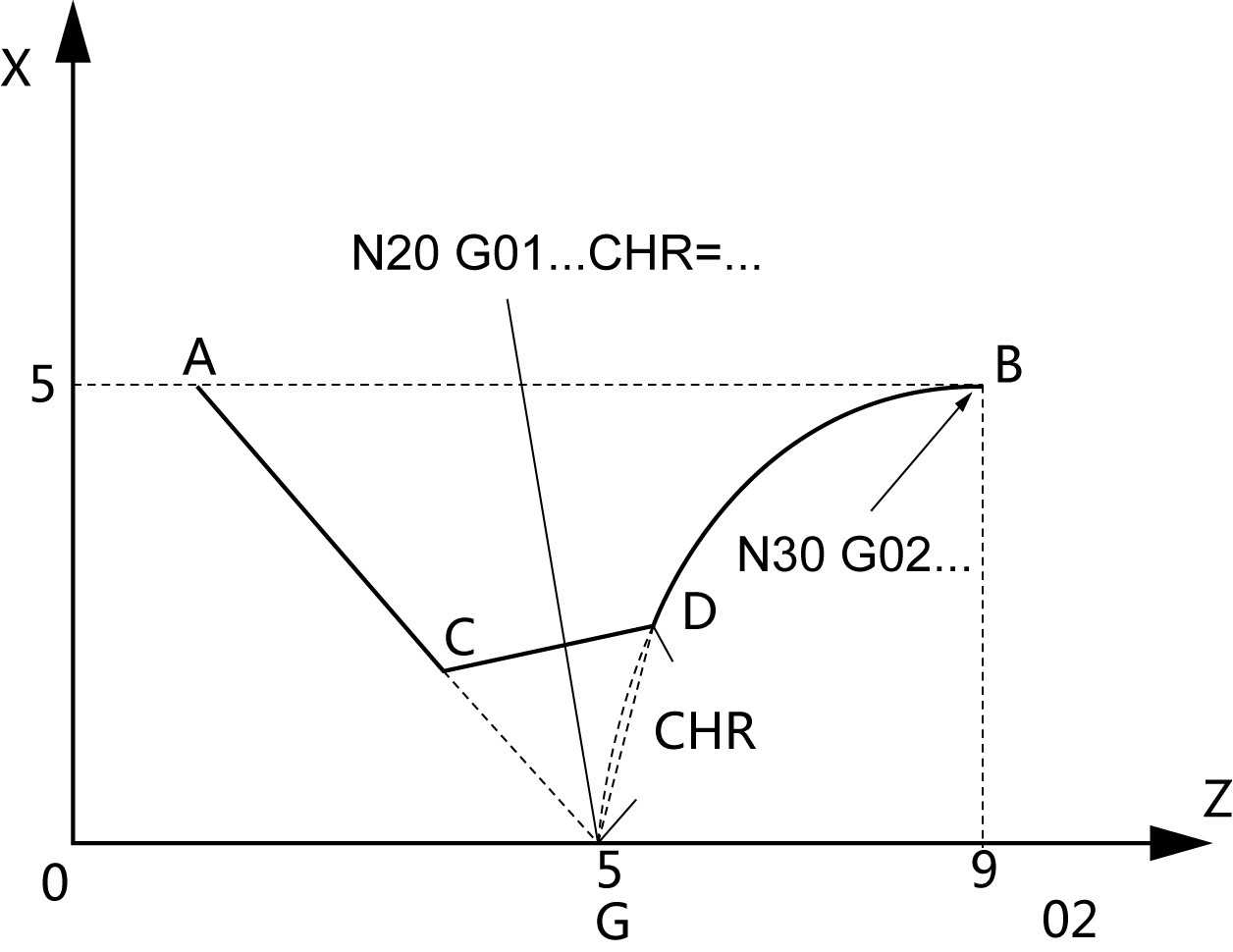
Fig.2.20 Inserting a chamfer with CHR: Between straight line and arc
N10 G94 G01 X5 Z1 F100
N20 G01 Z5 X0 CHR=1
N30 G02 Z9 X5 CR=...

Fig.2.21 Inserting a chamfer with CHR: Between arc and straight line
N10 G94 G01 X5 Z0 F100
N20 G02 Z5 X0 CR=... CHR=1
N30 G01 Z10 X5
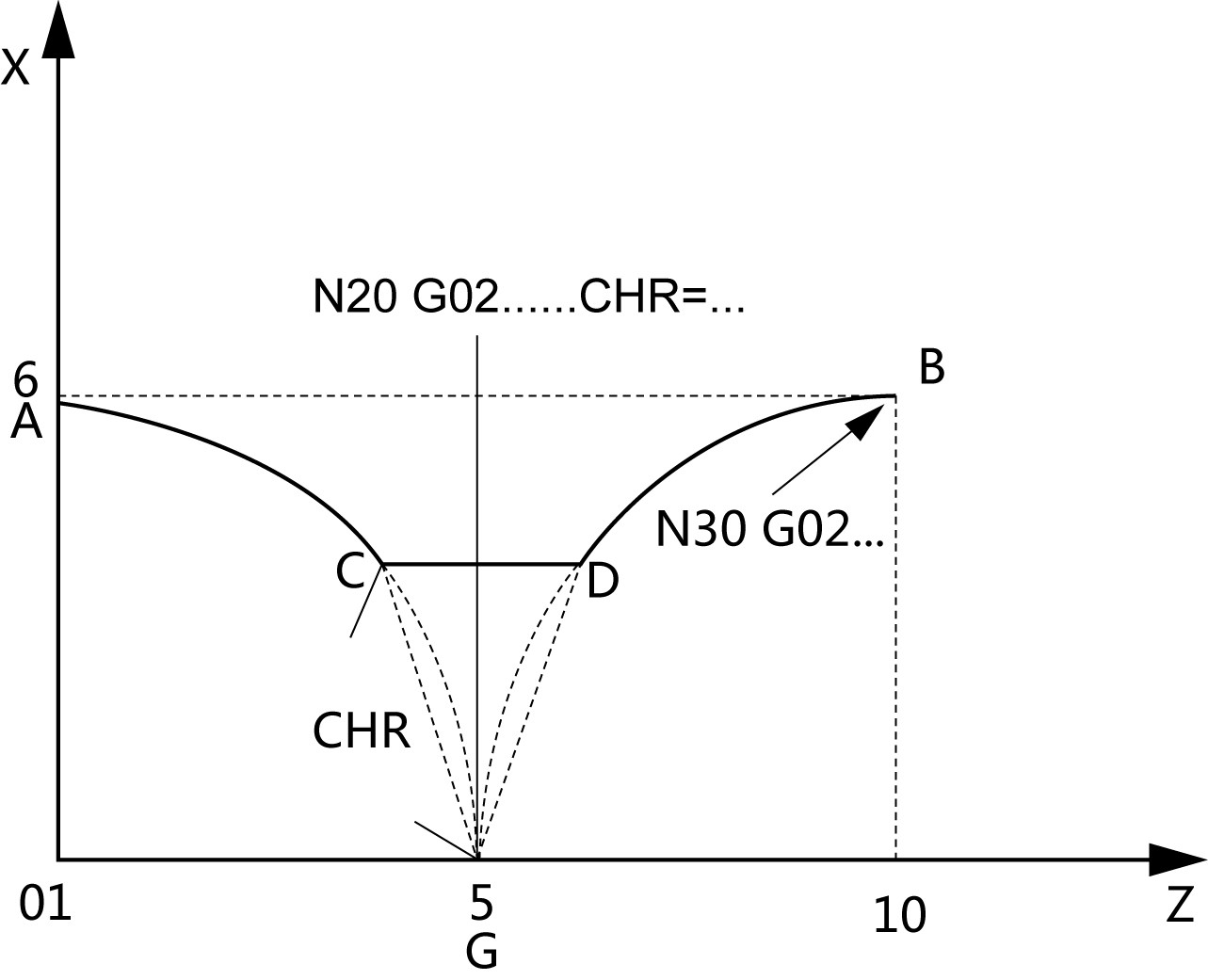
Fig.2.22 Inserting a chamfer with CHR: Between two arcs
N10 G94 G01 X6 Z0 F100
N20 G02 Z5 X0 CR=...CHR=1
N30 G02 Z10 X6 CR=...
2. CHF chamfer
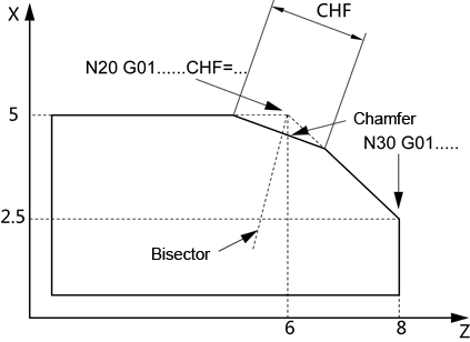
Fig.2.23 Inserting a chamfer with CHF: Between two straight lines
N10 G94 G01 X5 Z1 F100
N20 G01 X5 Z6 CHF=1
N30 G01 X2.5 Z8
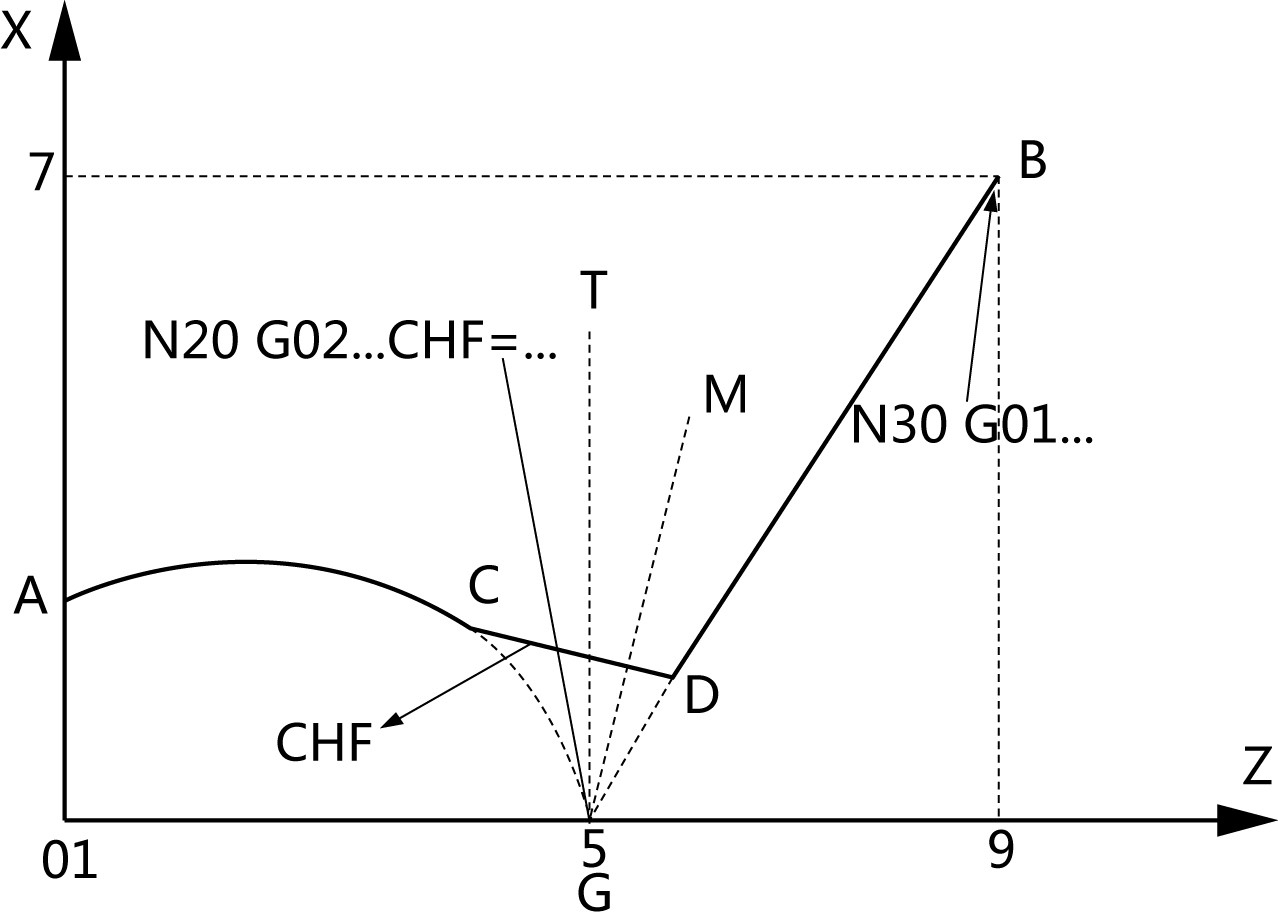
Fig.2.24 Inserting a chamfer with CHF: Between arc and straight line
N10 G94 G01 X2 Z0 F100
N20 G02 Z5 X0 CR=... CHF=1 F100
N30 G01 Z9 X7
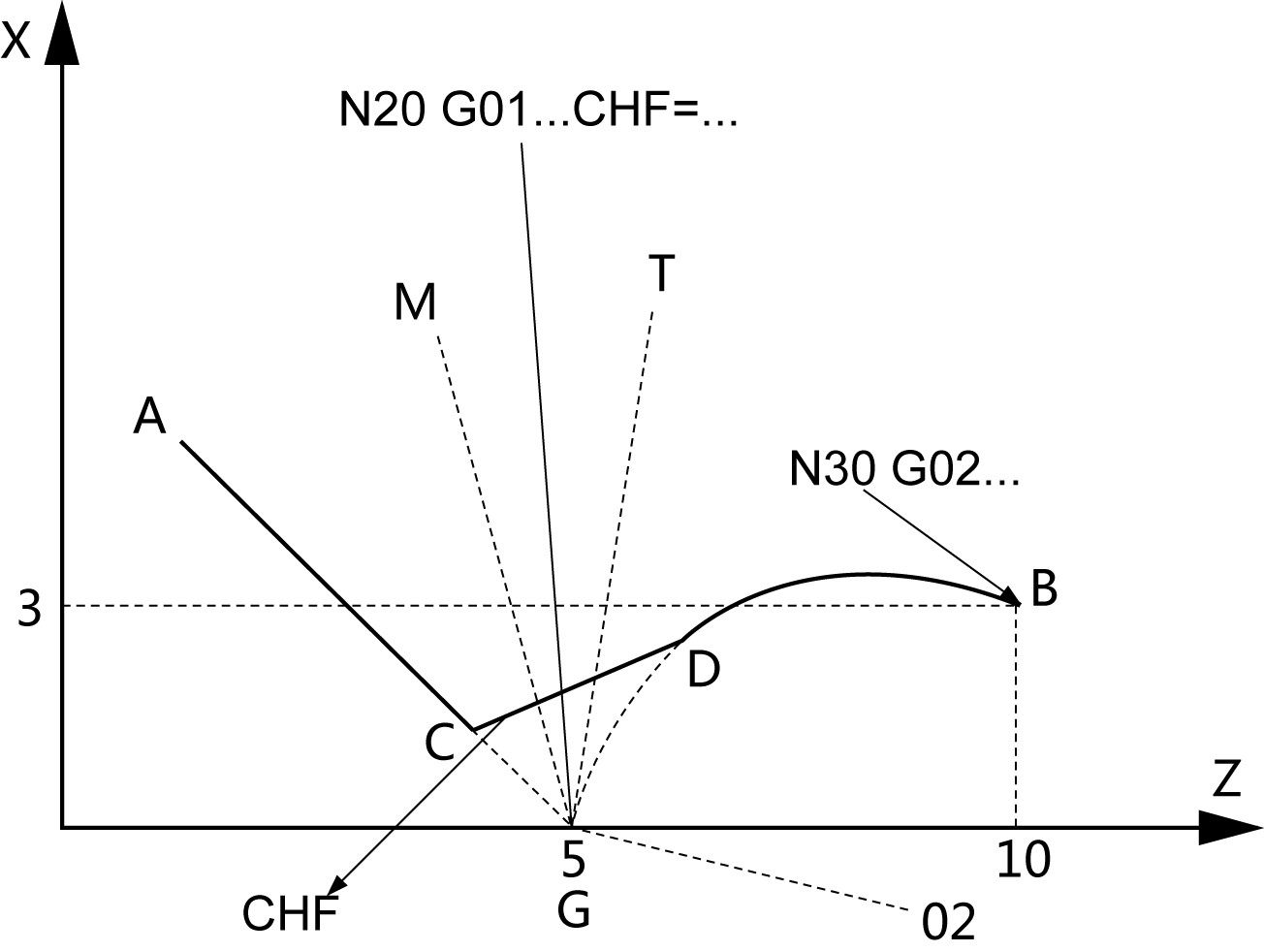
Fig.2.25 Inserting a chamfer with CHF: Between straight line and arc
N10 G94 G01 X5 Z1 F100
N20 G01 Z5 X0 CHF=1
N30 G02 Z10 X3 CR=...
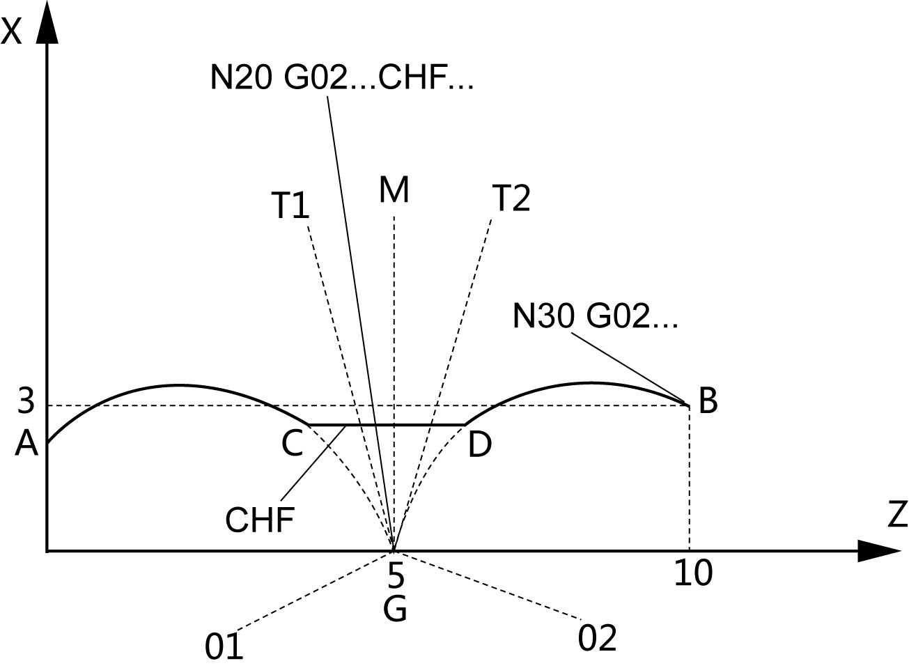
Fig.2.26 Inserting a chamfer with CHF: Between two arcs
N10 G94 G01 X2 Z0 F100
N20 G02 Z2 X0 CR=... CHF=1
N30 G02 Z10 X3 CR=…
3. RND Rounding
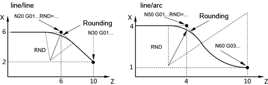
Fig.2.27 Examples for inserting roundings
N10 G94 G01 X6 Z0 F100
N20 G01 X6 Z6 RND=5
N30 G01 X2 Z10
……
N40 G01 X4 Z0 F100
N50 G01 X4 Z4 RND=10
N60 G03 X1 Z10 CR=10
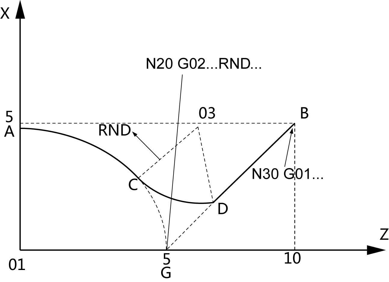
Fig.2.28 Examples for inserting roundings
N10 G94 G01 X5 Z0 F100
N20 G02 Z5 X0 CR=… RND=2
N30 G01 Z10 X5
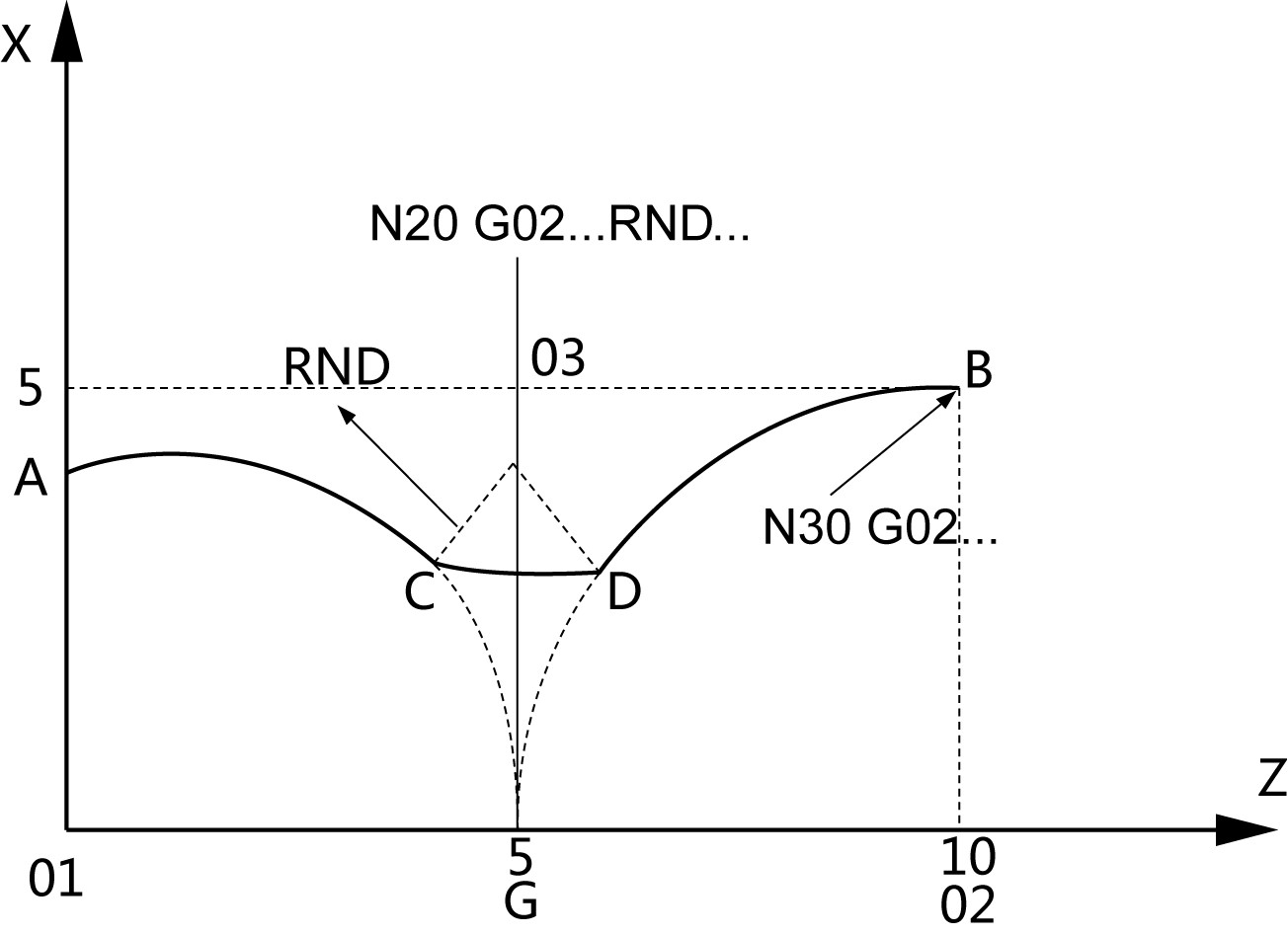
Fig.2.29 Examples for inserting roundings
N10 G94 G01 X4 Z0 F100
N20 G02 Z5 X0 CR=… RND=2
N30 G02 Z10 X5 CR=…
