2.4 Installation of Driver, Motor and Accessories
2.4.1 Installation of Yaskawa ∑-V Servo-driver
2.4.1.1 Installation direction
There are 3 kinds of servo-unit Installation: Base mount type, Shelf mount type and Pipeline mount type。As illustrated below, no matter what kind of installation, the installation direction should be perpendicular to the direction of the wall. The servo-unit should be firmly fixed to the mounting surface by using 2-4 mounting holes (mounting holes number varies according to the capacity of servo-unit).
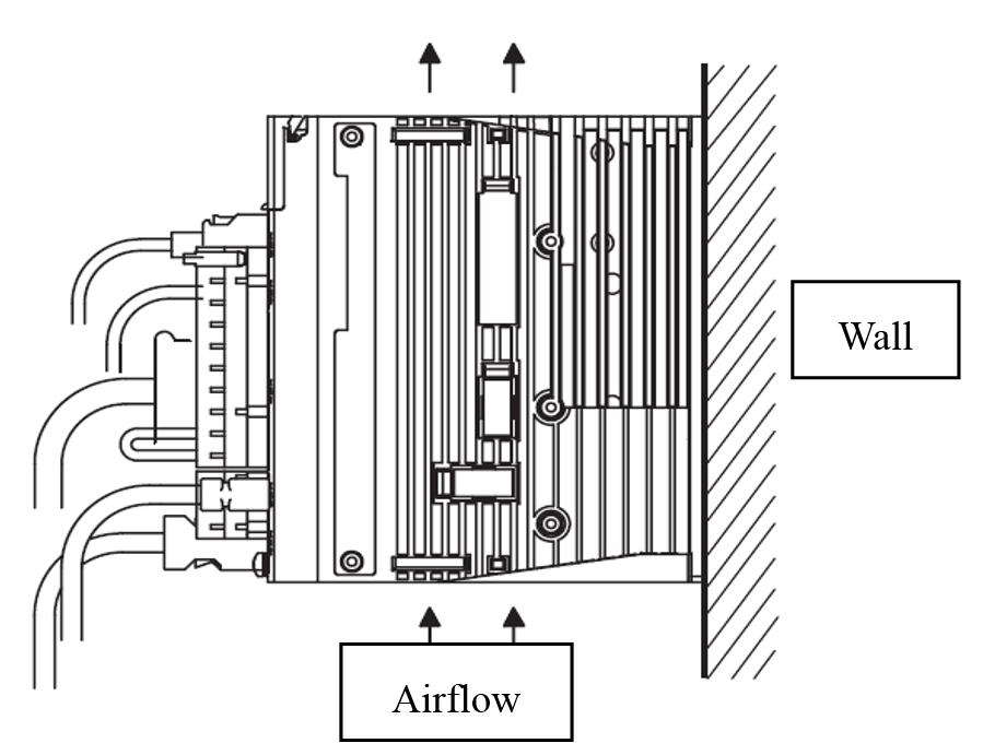
Figure 2.6 Installation direction of Yaskawa ∑-V Servo-driver
2.4.1.2 Installation standards
Be sure to install the servo-unit shown below in compliance with the control cabinet installation standards, this standard also suitable for multiple servo-units mounted side by side in the control cabinet.
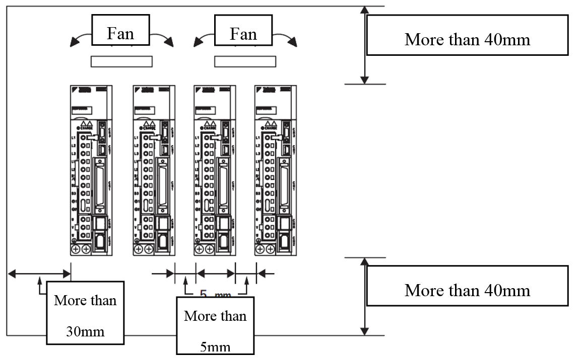
Figure 2.7 Installation of requirements Yaskawa ∑-V Servo-driver
2.4.1.3 Corresponding servo-driver dimensions

Figure 2.8 Three-phase AC200V SGDV-120A0xA
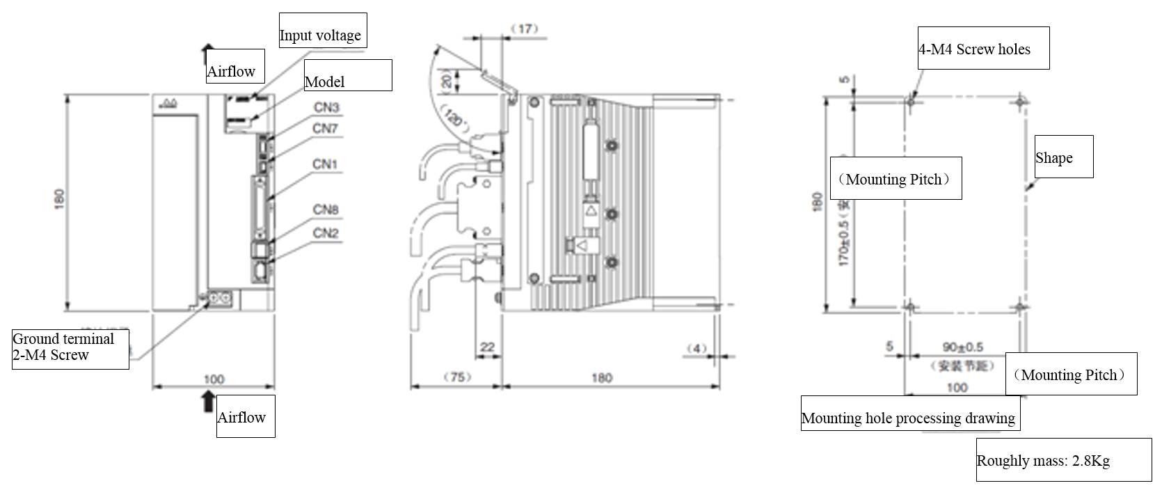
Figure 2.9 Three-phase AC200V SGDV-180A0xA、-200A0xA
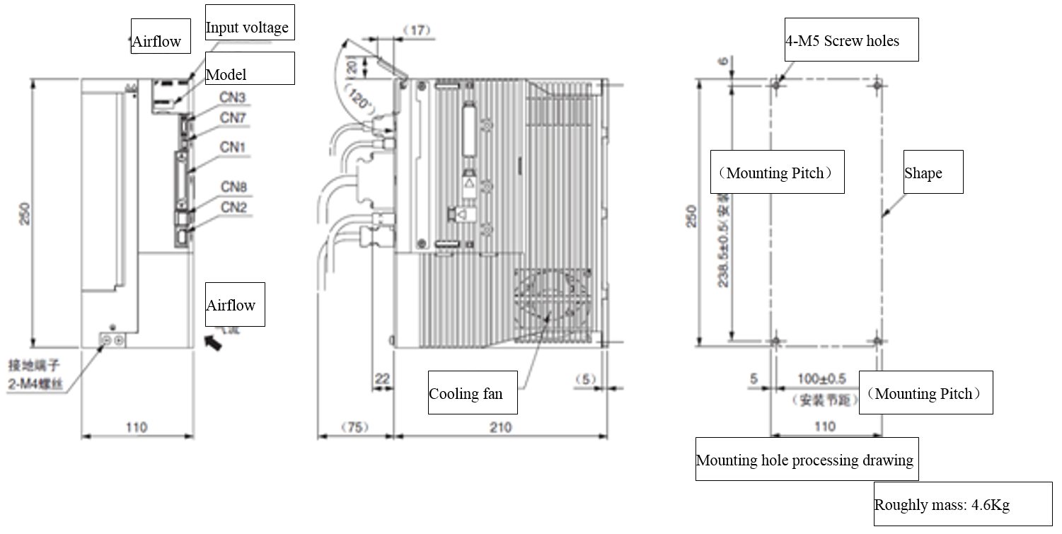
Figure 2.10 Three-phase AC200V SGDV-330A0xA
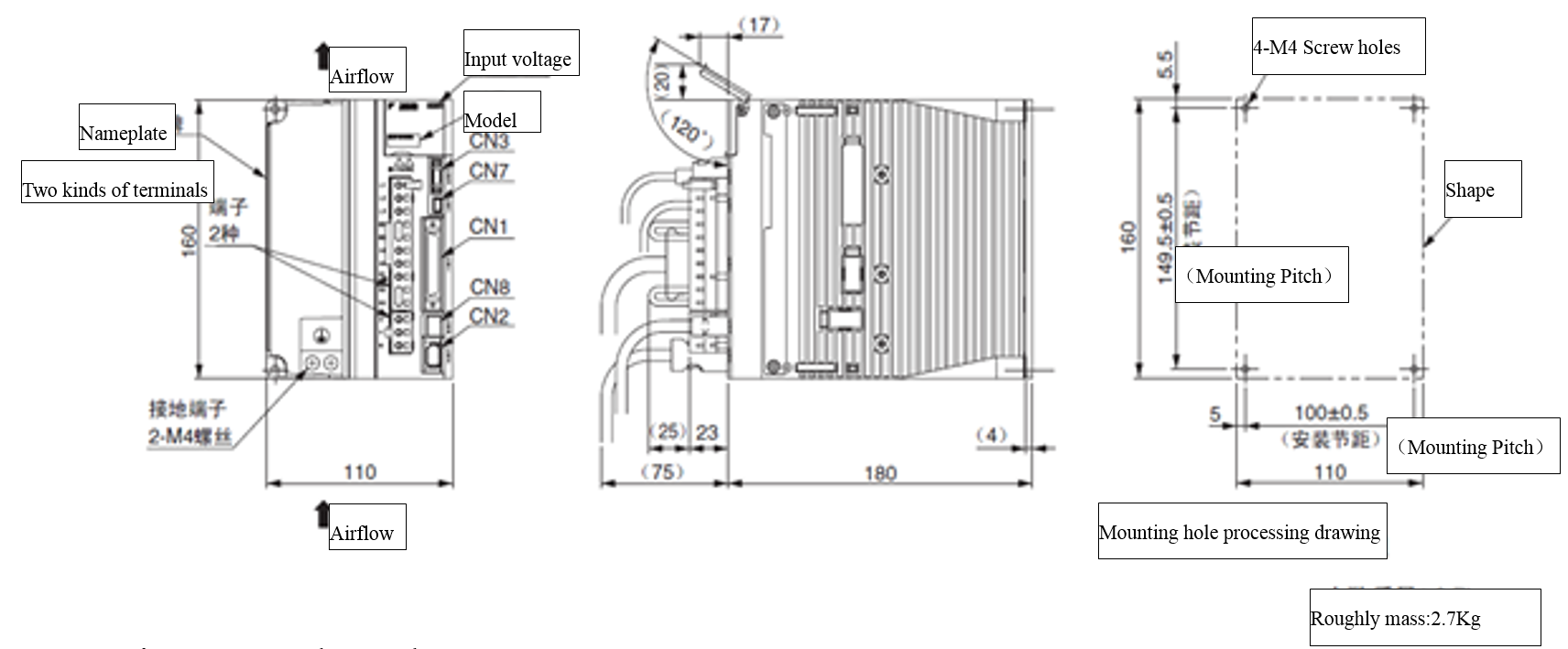
Figure 2.11 Three-phase AC400V SGDV-5R4D0xA
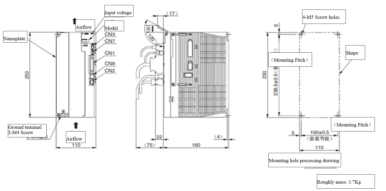
Figure 2.12 Three-phase AC400V SGDV-8R4D0xA、-120D0xA
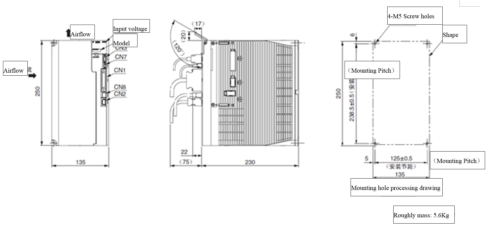
Figure 2.13 Three-phase AC400V SGDV-170D0xA
2.4.1.4 Installation dimensions of Motor
Installation without Brake
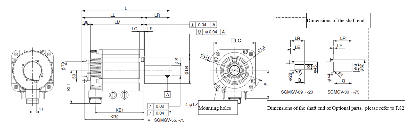
Figure 2.14 Installation dimensions of Yaskawa Motor (without Brake)
Table 2.1 Installation dimensions of Yaskawa Motor (without Brake)
|
Model SGMGV- |
L |
LL |
LM |
LR |
KB1 |
KB2 |
KB3 |
IE |
KL1 |
- |
|
13XXA2X |
211 |
153 |
117 |
58 |
99 |
177 |
131 |
- |
104 |
- |
|
20XXA2X |
229 |
171 |
135 |
58 |
117 |
195 |
149 |
- |
104 |
- |
|
30XXA2X |
239 |
160 |
124 |
79 |
108 |
196 |
148 |
- |
134 |
- |
|
44XXA2X |
263 |
184 |
148 |
79 |
132 |
220 |
172 |
- |
134 |
- |
|
Model SGMGV- |
Flange surface dimension |
Shaft end dimension |
Approximate Mass |
|||||||
|
LA |
LB |
LC |
LE |
LG |
LH |
LZ |
S |
Q |
||
|
13XXA2X |
145 |
|
130 |
6 |
12 |
165 |
9 |
|
40 |
9.0 |
|
20XXA2X |
145 |
|
130 |
6 |
12 |
165 |
9 |
|
40 |
11.0 |
|
30XXA2X |
200 |
|
180 |
3.2 |
18 |
230 |
13.5 |
|
76 |
19.5 |
|
44XXA2X |
200 |
|
180 |
3.2 |
18 |
230 |
13.5 |
|
76 |
23.5 |


Installation with Brake
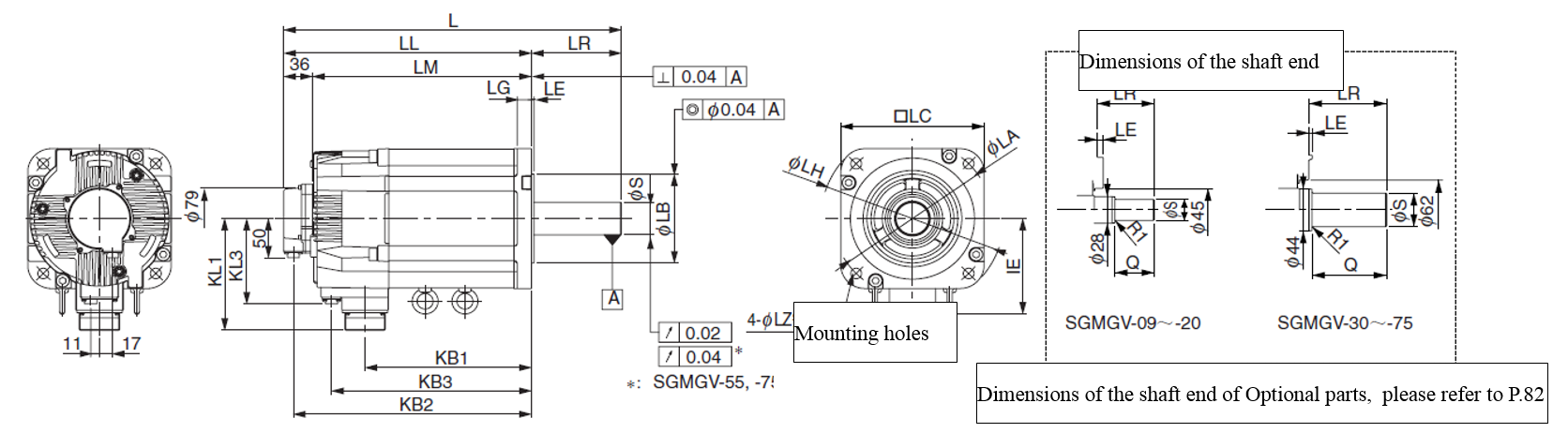
Figure 2.15 Installation dimensions of Yaskawa Motor (with Brake)
Table 2.2 Installation dimensions of Yaskawa Motor (with Brake)
|
Model SGMGV- |
L |
LL |
LM |
LR |
KB1 |
KB2 |
KB3 |
IE |
KL1 |
KL3 |
|
13XXA2X |
247 |
189 |
153 |
58 |
99 |
177 |
131 |
- |
104 |
80 |
|
20XXA2X |
265 |
207 |
171 |
58 |
117 |
195 |
149 |
- |
104 |
80 |
|
30XXA2X |
287 |
208 |
172 |
79 |
108 |
196 |
148 |
- |
134 |
110 |
|
44XXA2X |
311 |
232 |
196 |
79 |
132 |
220 |
172 |
- |
134 |
110 |
|
Model SGMGV- |
Flange surface dimension |
Shaft end dimension |
Approximate Mass |
|||||||
|
LA |
LB |
LC |
LE |
LG |
LH |
LZ |
S |
Q |
||
|
13XXA2X |
145 |
|
130 |
6 |
12 |
165 |
9 |
|
40 |
9.0 |
|
20XXA2X |
145 |
|
130 |
6 |
12 |
165 |
9 |
|
40 |
11.0 |
|
30XXA2X |
200 |
|
180 |
3.2 |
18 |
230 |
13.5 |
|
76 |
19.5 |
|
44XXA2X |
200 |
|
180 |
3.2 |
18 |
230 |
13.5 |
|
76 |
23.5 |


2.4.2 Installation of HSHA driver
2.4.2.1 Installation dimensions
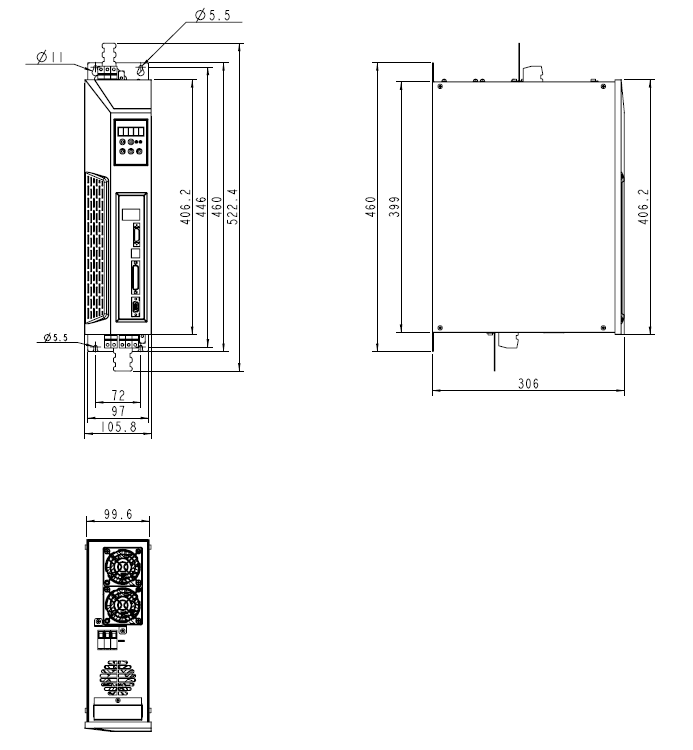
Figure 2.16 Installation dimension of HSHA
2.4.2.2 Installation requirements
In the Shelf mount type, there is a mounting hole of each of the four corners about the Driver rear panel. By using these mounting holes, the driver can be fixed firmly to the vertical surface
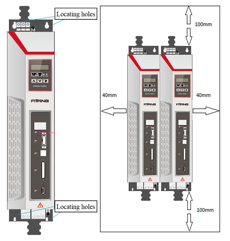
Figure 2.17 Installation requirements of HSHA driver
1. Please vertically install the driver, and make sure that there is enough space around it for ventilation;when necessary, install electric fan to make sure that the temperature in the control cabinet is below 40 ℃;
2. When assembling control cabinet, do not let metal chips into the Servo-driver;
3. Do not let oil, water, metal chips and other things from the control cabinet slots or electric fan into the Servo-driver;
4. When installing the control cabinet in the place with noxious gases and dusts, to prevent these substances into the control cabinet, it should have forced ventilation (send clean air into the control cabinet, so that the internal pressure is higher than the external pressure).
2.4.2.3 Braking resistor dimensions
The corresponding models
Table 2.3 Corresponding Braking resistor models of the Drivers
|
Servo-driver Model |
Braking resistor value |
Power of the Resistor |
|
HSHA-025-A |
70ohm |
500W |
|
HSHA-050-A |
70ohm |
750W |
|
HSHA-075-A |
50ohm |
1KW |
Shape of Braking resistor
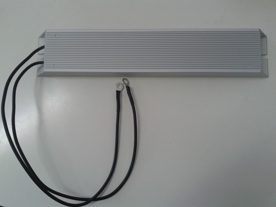
Figure 2.18 RXLG-500W-70ohm


Figure 2.19 RXLG-750W-70ohm
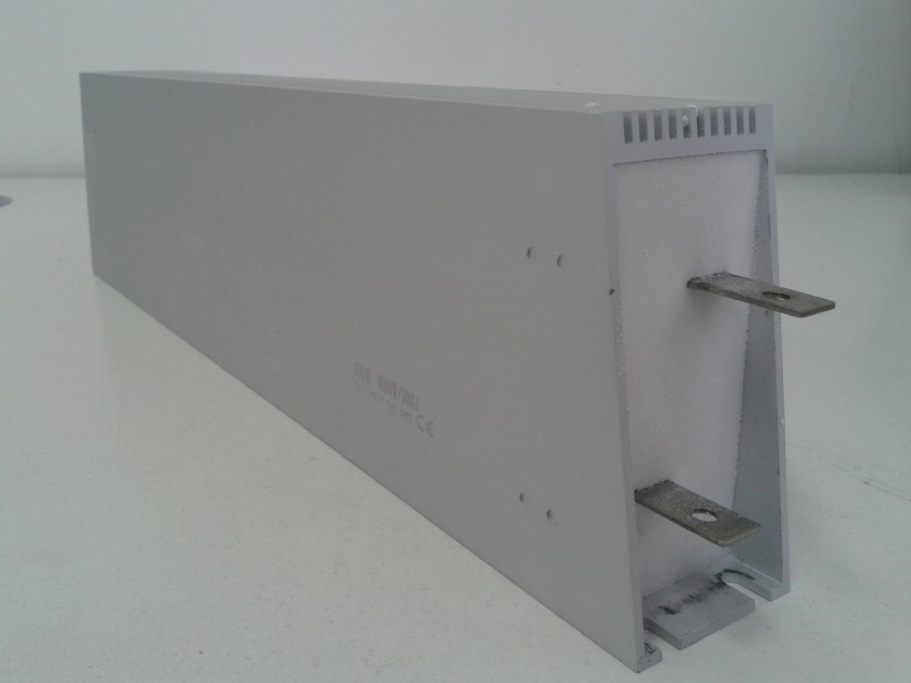
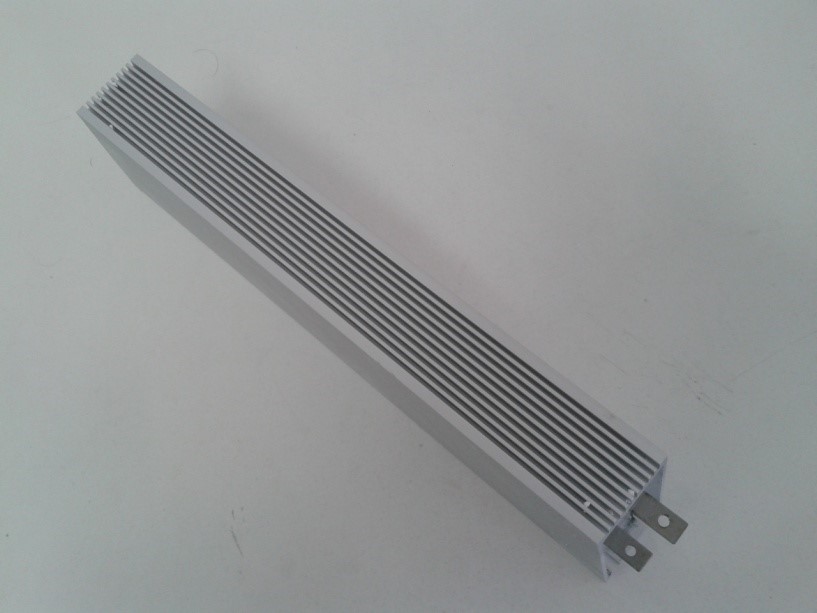
Figure 2.20 RXLG-1000W-50ohm
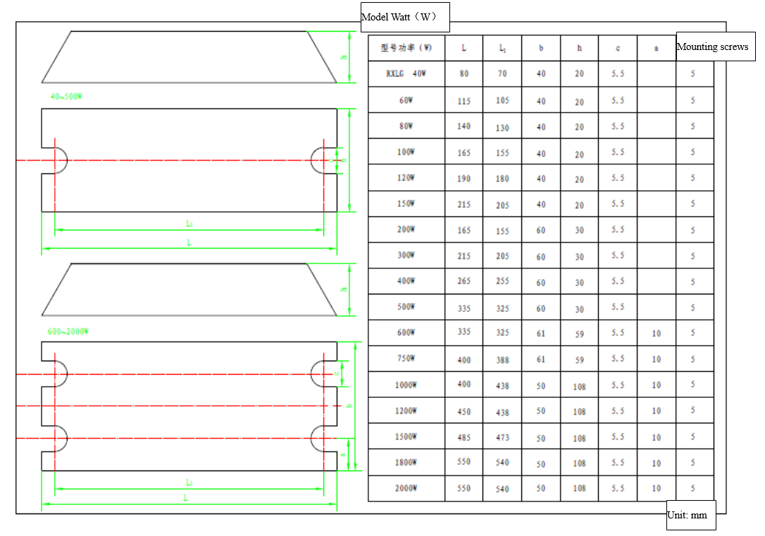
Size of braking resistor
2.4.3 Installation of CTB Spindle driver
2.4.3.1 Installation directions and requirements
When more than one driver are installed in the control cabinet, these drivers should be mounted side by side, and the air inlet, outlet and a dedicated cooling fan are necessary; when the upper and lower installation type is chosen, the installation of diversion partition between the drivers is also necessary to ensure that the cooling is effective.
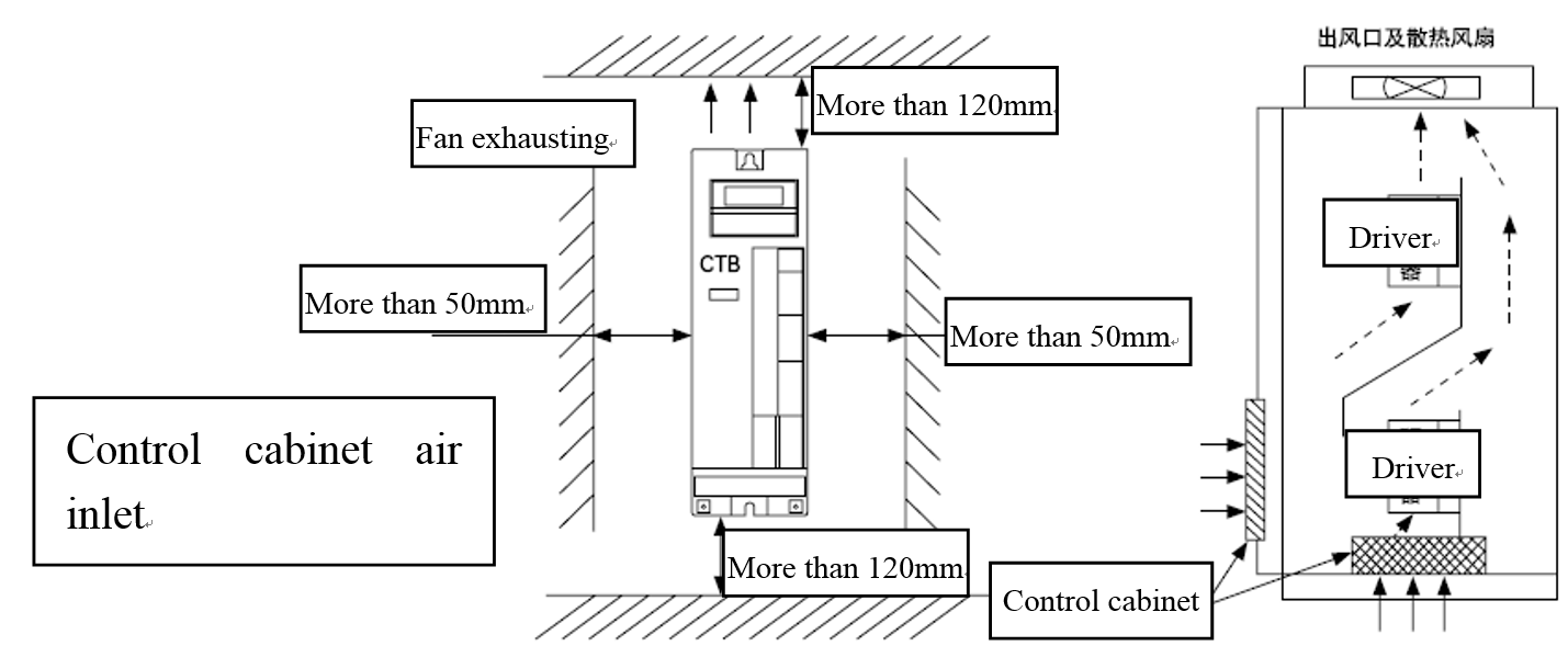
Figure 2.21 Installation directions and requirements of CTB driver
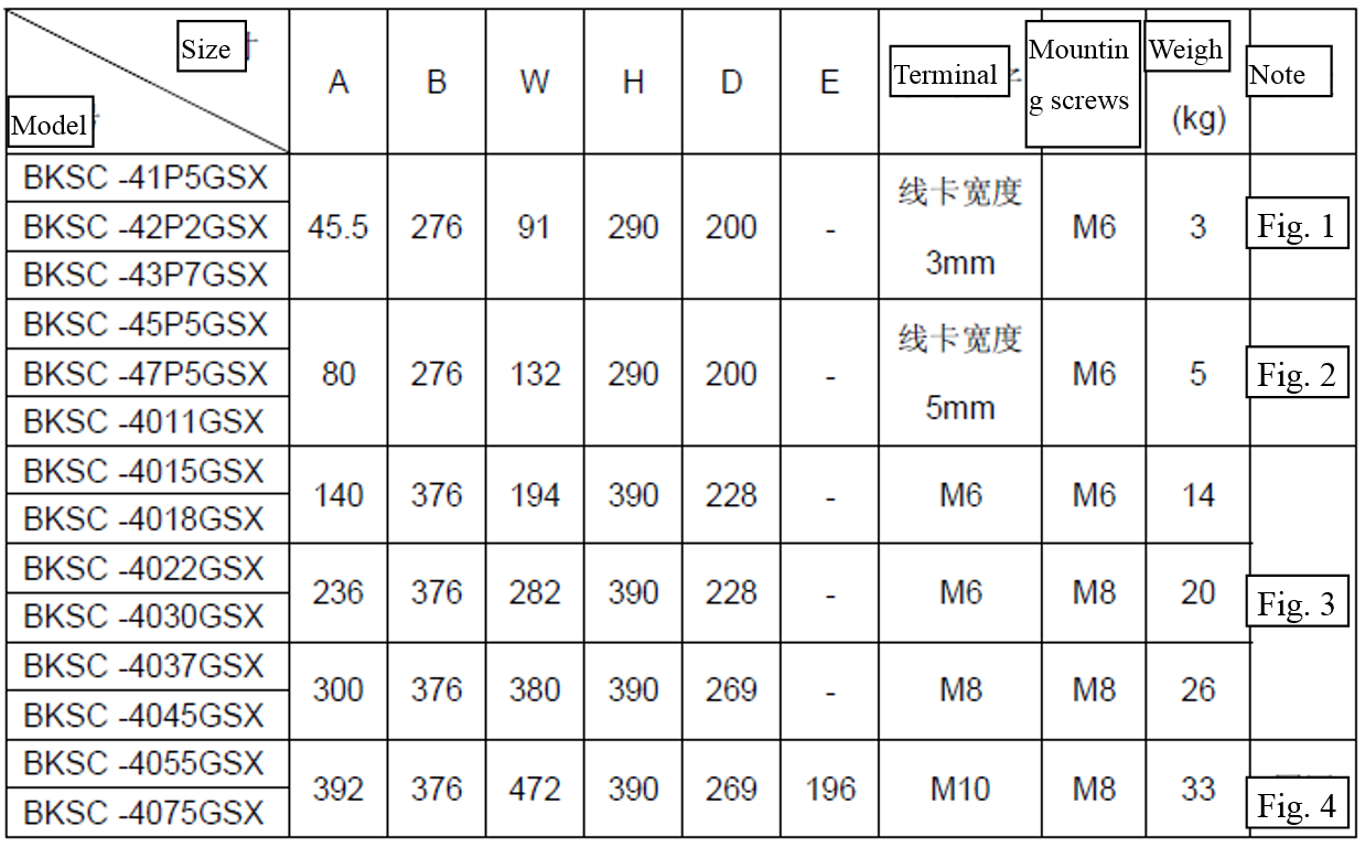
2.4.3.2 Size of the driver
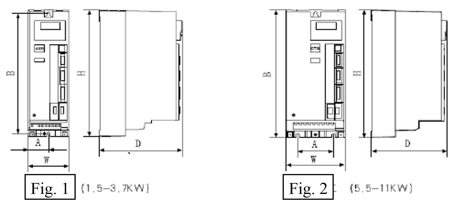
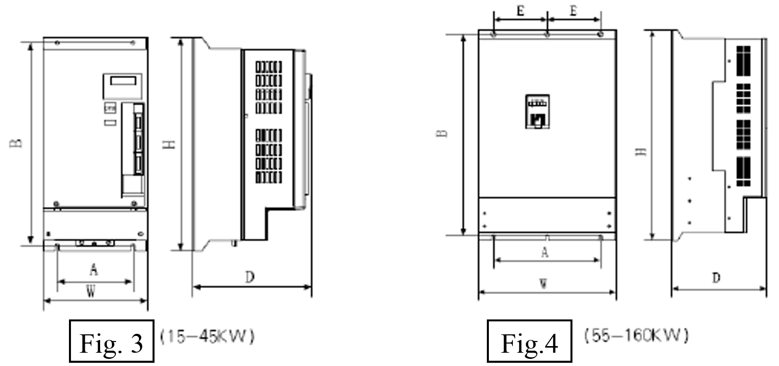
Figure 2.22 Installation dimensions
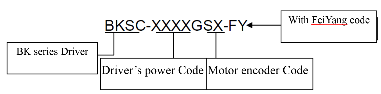
The driver models
2.4.3.3 Dimensions of the motors
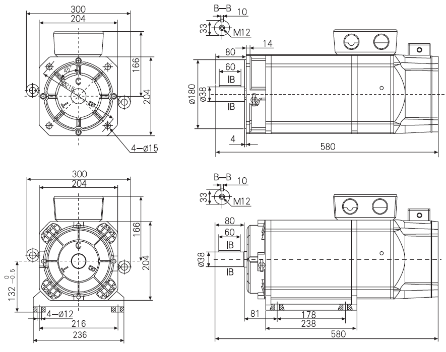
Figure 2.23 Dimensions of the 7.5KW motor
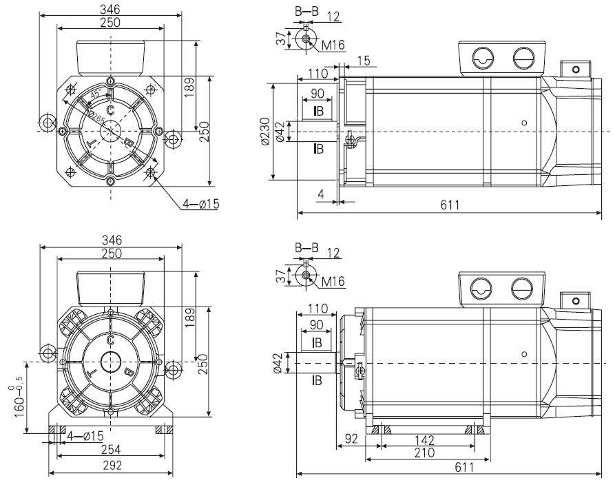
Figure 2.24 Dimensions of the 11KW motor

Figure 2.25 Dimensions of 15KW motor
2.4.4 Installation of TDE Spindle driver
2.4.4.1 Dimensions of the driver

Figure 2.26 Dimensions of the OPDE V15A driver
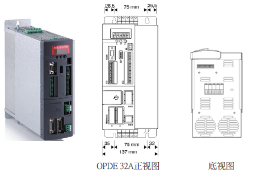
Figure 2.27 Dimensions of the OPDE V32A driver
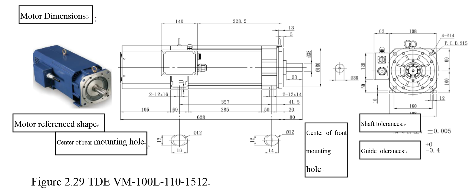
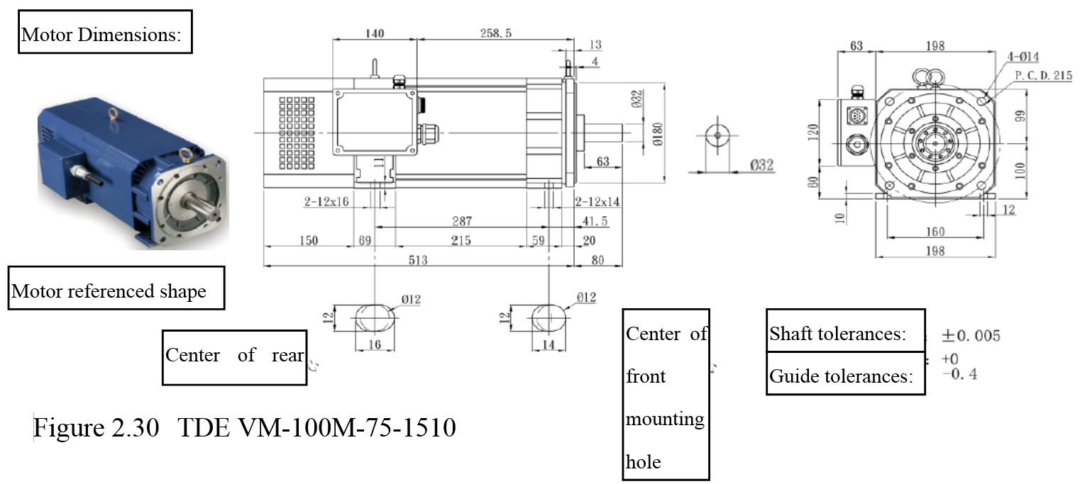
2.4.4.2 Size of corresponding motors
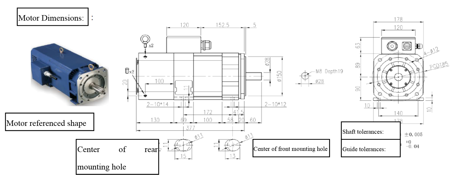
Figure 2.28 TDE VM-90M-37-2010