

3.3 Definitions and Wring of PLC Board Interface
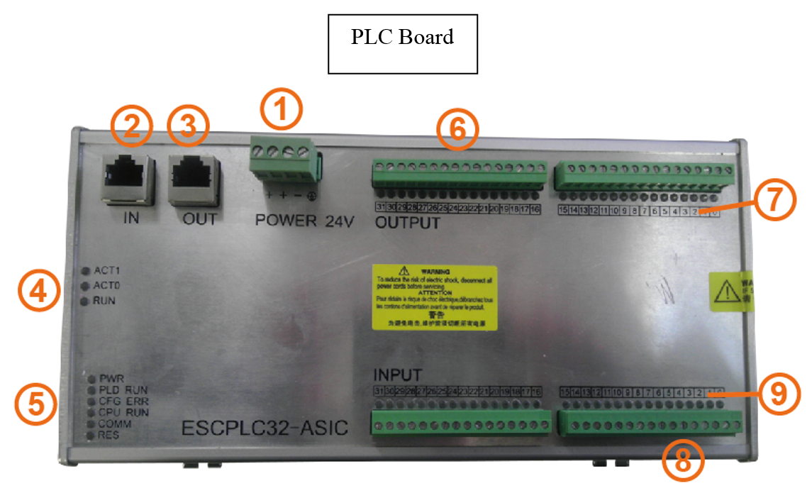
Figure 3.9 PLC Board
3.3.1 Basic Specifications
Table 3.8 Basic parameters of PLC Board
|
Storage and transportation conditions |
|
|
Temperature |
-40~70℃ |
|
Relative Humidity |
<=95%, No condensation |
|
Atmospheric pressure |
70~106kpa |
|
Sinusoidal Vibration |
<=10 m/s2 , Three-axis direction Acceleration |
|
Random Vibration |
<=1 M2/s3,Acceleration spectral density |
|
Allowed drop height |
<=1 M |
|
Others |
No corrosive gases, No dust |
|
Working conditions |
|
|
Temperature |
5~45℃ |
|
Relative humidity |
10%~95%,No condensation |
|
Atmospheric pressure |
80~106kpa |
|
Sinusoidal vibration |
<=10 m/s2,Three-axis direction Acceleration |
|
Vibration frequency |
<=900Hz |
|
Random Vibration |
<=1 M2/s3,Acceleration spectral density |
|
Others |
No corrosive gases, No dust |
3.3.2 Interface definitions
Figure 3.9 Interface definitions of PLC Board
|
Number |
Name |
Technical description |
|
1 |
Power-supply interface |
DC 24V(It is better by using two + terminals power-supply when the output load is large) |
|
2 |
ECAT Bus input interface |
Recommend: port IN access output port of the front ECAT controller, port OUT access input port of the rear ECAT controller. |
|
3 |
ECAT Bus output interface |
|
|
4 |
Bus state indicators |
See the following table about Bus state indicators definition |
|
5 |
Board state indicators |
See the following table about Board state indicators definition |
|
6 |
Digital output interface |
PLC32:with 32 input ports and 32 output ports PLC48:with 48 input ports and 48 input ports |
|
8 |
Digital output interface |
|
|
7 |
Digital output state indicator |
When interface is in state of logic level '1', the corresponding LED is ON. Otherwise the corresponding LED is OFF. |
|
9 |
Digital input state indicator |
3.3.3 Bus State indicators
Figure 3.10 Bus State indicators
|
LED Name |
Function |
State |
Meaning |
|
ACT1 |
Connection state of OUT port |
OFF |
OUT port is NOT effectively connected with other devices |
|
Constantly ON |
OUT port is effectively connecting with other devices |
||
|
Blinking |
OUT port is communicating with other devices |
||
|
ACT0 |
Connection state of IN port |
The same as ACT1 |
The same as ACT1 |
|
RUN |
Bus State indicators |
OFF |
Board is not established connection with Bus, or it is in the INIT state. |
|
Blinking |
Board-Bus is in the PRE-OP state, it is an intermediate state when the power is on. |
||
|
Constantly ON |
Board-Bus is in the OP state, which is the state of normal operation |
3.3.4 State indicators of PLC Board
Table 3.11 State indicators of PLC Board
|
LED Name |
Function |
State |
Meaning |
|
PWR |
Power indicator |
Constantly ON |
Board power supply is in normal. |
|
PLD RUN |
Port IO working state |
Blinking |
Port IO Chip is working in normal. |
|
CFG ERR |
Bus configuration state |
OFF |
Bus control chip is configured in normal. |
|
ON |
Bus control chip is configured in ERROR |
||
|
CUP RUN |
Board CPU working state |
Blinking |
Board control chip is working in normal. |
|
COMM |
Communication state indicator |
OFF |
No process data is exchanging between the Board and the main station. |
|
Constantly ON with low luminance |
Process data is exchanging between the Board and the main station. |
||
|
RES |
Reserved |
|
|
3.3.5 Wiring examples and Principles of Interface
Overview

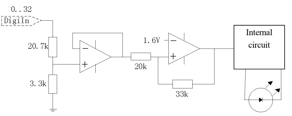
Figure 3.10 Wiring of the PLC Board
Interface circuit
ESCPLC-ASIC-V1.3 has the input with 24V electrical level, and the input signal and the power supply of the entire Board interface are grounded together. Its basic parameters are as follows:
|
ESCPLC32-ASIC-V1.3 |
32 digits inputs, 32 digits outputs |
|
ESCPLC48-ASIC-V1.3 |
32 digits inputs, 32 digits outputs |
The input signal is a kind of level input, and the signal should be grounded together with the power signal of the Board interface. The typical input current is <2mA. It is suitable for driving small power relays and LED. See more in the following figure:
|
Electrical level or Voltage |
State: |
|
Vin>19V |
Logic '1' |
|
6V<Vin<19V |
The same as former logic state |
|
Vin<6V |
Logic '0' |
The output signal is driven by transistor, and its driving current is from the power supply of Board interface. The referential electrical level is from the negative pole of the power supply of the Board. The driving voltage is 24V, and maximum driving current is 200mA, so it can be used only to drive small power relays and signal lights. See more in the following figure:

|
The output logic state |
The output voltage |
|
Logic '1 ' |
VCC(24V power supply voltage of the Board), Output Current is <200mA |
|
Logic '0 ' |
<1V |
Wiring example of the PLC Board
 Figure 3.11 Wiring example of the PLC Board
