

3.2 Definitions and Wiring of DAC Board Interface

Figure 3.5 DAC Board
3.2.1 Basic parameters
Table 3.3 Basic parameters of DAC
|
Storage and transportation conditions |
|
|
Temperature |
-40~70℃ |
|
Relative humidity |
<=95%,No condensation |
|
Atmospheric pressure |
70~106kpa |
|
Sinusoidal vibration |
<=10 m/s2, Three-axis direction Acceleration |
|
Random Vibration |
<=1 M2/s3,Acceleration spectral density |
|
Allowed drop height |
<=1 M |
|
Others |
No corrosive gases, No dust |
|
Working conditions |
|
|
Temperature |
5~45℃ |
|
Relative humidity |
10%~95%,No condensation |
|
Atmospheric pressure |
80~106kpa |
|
Sinusoidal vibration |
<=10 m/s2,Three-axis direction Acceleration |
|
Vibration frequency |
<=900Hz |
|
Random Vibration |
<=1 M2/s3,Acceleration spectral density |
|
Others |
No corrosive gases, No dust |
3.2.2 Interface definitions
Figure 3.4 Definitions of DAC Board interfaces
|
Number |
Name |
Technical description |
|
1 |
Power-supply interface |
DC 24V(It is better by using two + terminals power-supply, when the output load is large) |
|
2 |
ECAT Bus input interface |
Recommend: port IN access output port of the front ECAT controller, port OUT access input port of the rear ECAT controller. |
|
3 |
ECAT Bus output interface |
|
|
4 |
Bus state indicators |
See the following table about Bus state indicators definition |
|
5 |
Board state indicators |
See the following table about Board state indicators definition |
|
6 |
Servo interface |
4 identical servo interfaces, no primary or secondary. |
|
7 |
Emergency-stop button Interface |
|
|
8 |
Brake signal output interface |
4 interfaces, corresponding to the servo |
|
9 |
External encoder supply interface |
Using this interface for power supply when encoder needs power from Board. There is no protection device on the path of this interface to each of the servo interface, so if power protection is needed, please consider implementing it in the electrical circuit. |
3.2.3 Definitions of Servo interface
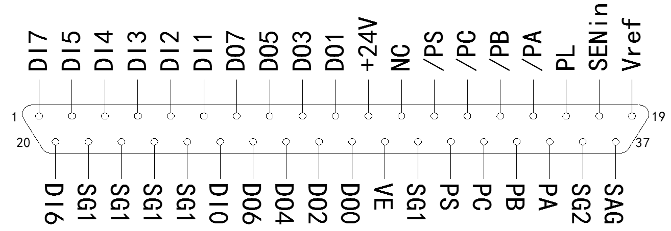
Table 3.5 Definitions of Servo interface
|
Pin Number |
Name |
Function |
Note |
|
Analog voltage output |
|||
|
19 |
Vref |
Analog voltage signal output(-10V~10V) |
|
|
37 |
SAG |
Analog voltage signal ground reference |
|
|
Digital input interface |
|||
|
25,6,5,4,3,2,20,1 |
DI0-DI7 |
Digital signal input |
|
|
21,22,23,24,31 |
SG1 |
Digital signal input grounding |
Connected with Pin 5 internally |
|
Digital Output Interface |
|||
|
29,10,28,9,27,8,26,7 |
DO0-DO7 |
Digital signal Output |
|
|
11 |
+24V |
Digital output power supply |
|
|
Incremental Encoder Interface |
|||
|
16 |
/PA |
Signal A inverting phase input |
|
|
35 |
PA |
Signal A positive phase input |
|
|
15 |
/PB |
Signal B inverting phase input |
|
|
34 |
PB |
Signal B positive phase input |
|
|
14 |
/PC |
Signal Z inverting phase input |
|
|
33 |
PC |
Signal Z positive phase input |
|
|
30 |
VE |
External encoder power input interface. It should be the same ground potential with SG1, if necessary,. |
Connected to the Board VE interface |
|
For future functions (absolute encoder) reserved, not supported. |
|||
|
13 |
/PS |
|
Do not use |
|
32 |
PS |
|
Do not use |
|
18 |
SENin |
|
Do not use |
|
17 |
PL |
|
Do not use |
|
36 |
SG2 |
|
Do not use |
3.2.4 Bus State indicators
Table 3.6 Bus State indicators
|
LED Name |
Function |
State |
Meaning |
|
ACT1 |
Connection state of OUT port |
OFF |
OUT port is not effectively connected with other devices |
|
Constantly ON |
OUT port is effectively connecting with other devices |
||
|
Blinking |
OUT port is communicating with other devices |
||
|
ACT0 |
Connection state of IN port |
The same as ACT1 |
The same as ACT1 |
|
RUN |
Bus State indicators |
OFF |
Board is not established connection with Bus, or it is in the INIT state. |
|
Quickly blinking |
Board-Bus is in the PRE-OP state, it is an intermediate state when the power is on. |
||
|
Slowly blinking |
Board is in the SAFE-OP state. Under normal circumstances, it lasts not long in this state. |
||
|
Constantly ON |
Board-Bus is in the OP state, which is the state of normal operation |
3.2.5 State indicators of DAC Board
Table 3.7 State indicators of DAC Board
|
LED Name |
Function |
State |
Meaning |
|
PWR |
Power indicator |
Constantly ON |
Board power supply is in normal. |
|
CFG ERR |
Bus configuration state |
OFF |
Bus control chip is configured in normal. |
|
Constantly ON |
Bus control chip is configured in error. |
||
|
CUP RUN |
Board CPU working state |
Blinking |
Board control chip is working in normal. |
|
COMM |
Communication state indicator |
OFF |
No process data is exchanging between the Board and the main station. |
|
Constantly ON with low luminance |
Process data is exchanging between the Board and the main station. |
||
|
PLD RUN |
Port IO working state |
Blinking |
Port IO Chip is working in normal. |
|
RES |
Reserved |
|
|
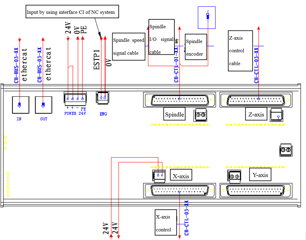
3.2.6 Wiring examples and Principles of Interfaces
3.2.6.1 Overview
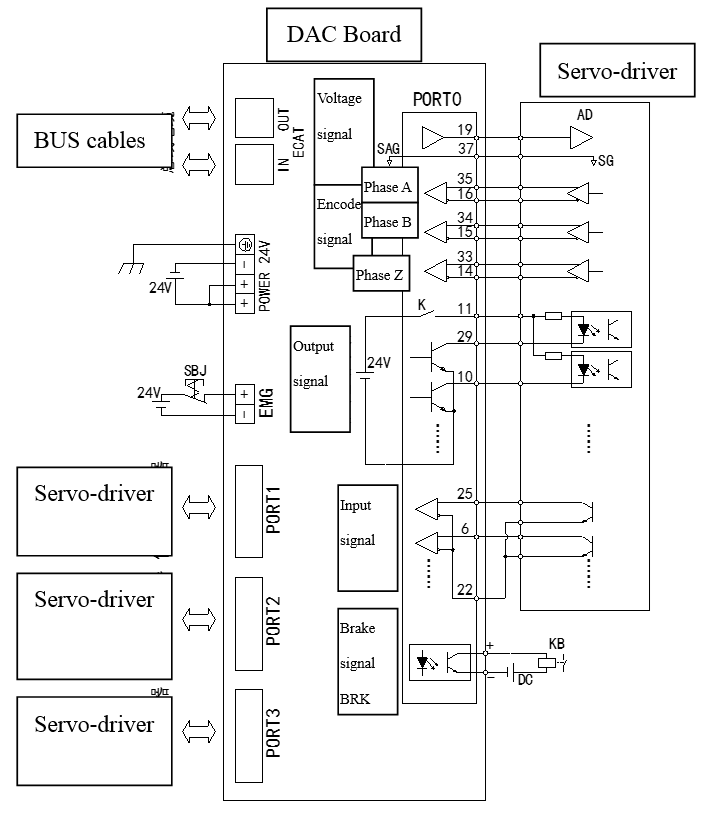
Figure 3.6 Wiring example of DAC Board
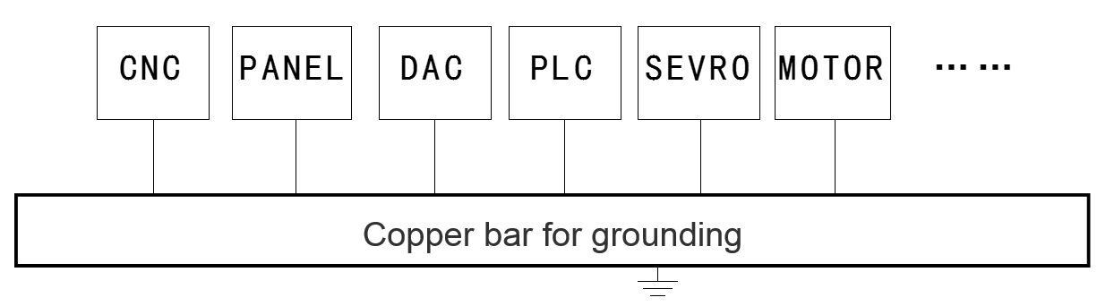
For safety reasons, the Board needs to be reliably grounded. Please pay attention to and distinguish the difference between the negative power and protective ground. But for ECAT Bus communication cable, it will reduce the capacity of resisting disturbance of the Bus when the shielding layer is not connected with accessories. Because the potential difference between the two ends of communication cable will generate current in the grounding shielding layer. Generally, it is recommended that the ECAT Bus cables are NOT shielded, If shielded cables are used, it is necessary that the cable shielding layer of the cables is connected with accessories. All devices in the system should be single-point grounded when it is possible, each grounding point of the Boards and the main station should be reliable and clean, and the resistance of grounding point should be less than 0.6Ω. Cross-sectional area of grounding cable (BVR specification) should be NOT less than 2mm2 if the cable is longer than 2m. Yellow standard grounding cable is recommended. And the recommended grounding method is as follows:
DAC Board is secondary control equipment, so it is better that the primary equipment and secondary equipment are placed in different areas during the cabinet layout.At the same time, secondary cable placed together with primary cable should also avoid.
3.2.6.2 Principles of Signal output interface
Each port of ESC-DAC16-CH4TTLI Board has one analog voltage output signal, this analog signal is used for speed control of the servo controller. Internal of the Board has precision operational amplifier for buffering, and the basic performance parameters are as follows:
|
Voltage range of the output |
±10V |
|
Minimum load resistor value |
4kΩ |
|
Resolution |
15 digits +1 sign digit(For DAC12: 11 digits+1signdigit) |
|
Open-loop accuracy |
≤±0.01V(In the range of±6V) |
|
Temperature drift |
0.004V/℃ |
Schematic diagram:
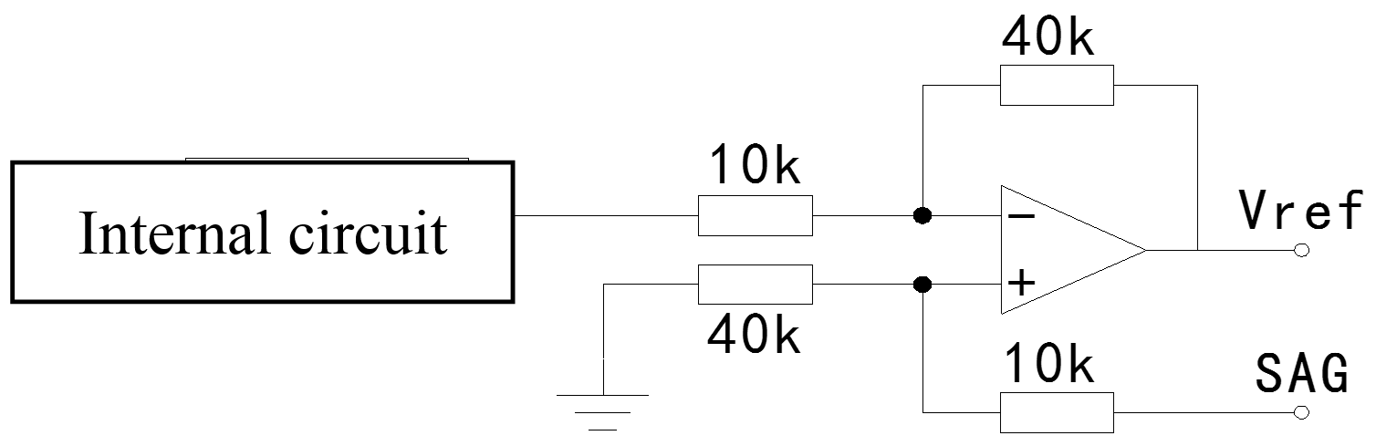
Based on the above, in most cases SAG should connect with the internal zero potential. For the Board, SAG should connect with SG1,and the method can be connecting to the plug of the Board or connecting with the remote devices. As for Yaskawa servo controller, because its analog and digital ground is connected together, it is equivalent that SAG and SG1 of the Board are connected remotely.
If the servo controller or other similar devices have compensational functions, it is available to connect the compensation voltage of the fixed potential to port SAG, acting as linear compensational function. But this function is seldom used.
3.2.6.3 Principles of Digital input interface
The input signal is passive signal input, inputs can be dry contact signals such as relay or switch, and transistor output structure is also available. If the output signal is in the form of dry contact, such as relay, the schematic diagram is shown below:
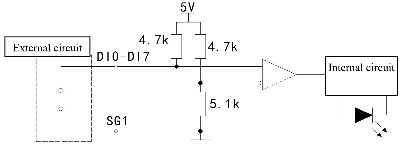
If transistor output is used, schematic diagram is as follows. For reliably working of the circuit, the forward saturated voltage-drop Uce of the transistor should be less than 2V when using transistor output. And most of the transistors are satisfied.
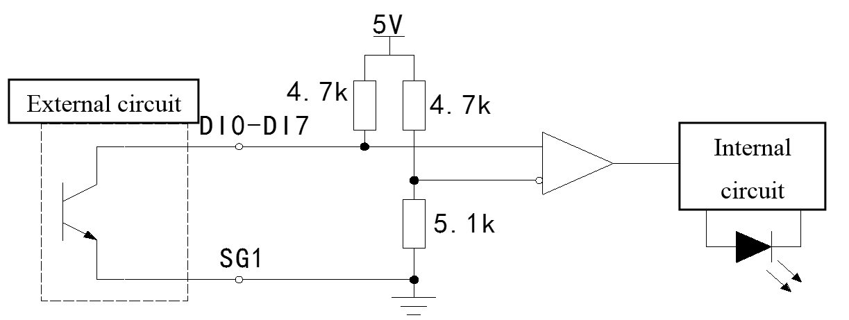 Based on the above principles, the state of the external input is opposite to the internal logic state. The internal logic state is '0 ' when the external device is enabled or action, which is manifested as the switch is closed, and vice versa. In the present version of software and hardware, there is also no treatment to these logic states inside the Board, and the Board directly sends the internal logic data to main station through the Bus. So in order to get the correct input state, these signals must be reversed before the ECAT main station uses these data. Therefore, in the case of the device is not connected to any servo, the input signals of the Board are all logic '1 ', and the corresponding input state indicators are all ON.
Corresponding logic states are as follows, but due to external needs passive contact signal, the following parameters are only for reference:
|
Interface Input Voltage(DI0-DI7) |
Internal logic states |
|
Vin>2.9V(External switches are OFF) |
Logic '1 ' |
|
2.3V<Vin<2.9V |
Uncertain |
|
Vin<2.3V(External switches are ON) |
Logic '0 ' |
3.2.6.4 Principles of Digital output interface
The output signal is driven by Dar1ington Transistor, which has common emitter and open collector structure. The Board provides 24V power supply for output interface. In the sinking current driving mode, the maximum current is 30mA, and the 50mA current can work only in short-term (for long-term working is not allowed). So it is only used to drive the equipments such as optocoupler primary side, light-emitting diodes, small power relays(Can not be used to drive high-power relay). When Darlington transistor is in saturation work, the positive saturation voltage Uce is approximately 1V.The schematic diagram is as follows:

The figure above, K is the safety relay contact, which is controlled by the normally closed contact of the emergency stop button, For more information you can refer to chapter 6.6. As far as possible to use the supplied 24V reference power-supply when the Board is using output interface. In the mode of using the reference power supply, when emergency stop button is pressed, K contacts will be open, at the same time the Board will stop power supply for the output ports, and all the external driven signals will be stopped to make sure that the servo-driver is also stopped. If the supplied 24V reference power-supply can not be used in the external devices, it has to be sure that the external device and the Board have the same ground level. (Realized by connecting the input signal ground SG1 to the external device power ground)But at same time the emergency stop functions of the Board can not be used, these additional functions can be realized on the electrical circuit.
JM4 is hard jumper, which is inside the Board, so it is necessary to open the Board case when try to change the jumper. The default state of the jumper is OFF, and it is considered that external emergency stop devices and related electrical circuits are already given. If there is no emergency stop button or the emergency stop button has no normally closed contact in the system, the related functions of emergency stop can not be used. In this situation, JM4 jumper should be shorted, and EMG interfaces on the Board should not be connected to any device. This emergency stop function can be realized on the electrical circuit when JM4 jumper is shorted.
3.2.6.5 Principles Of the encoder input interface
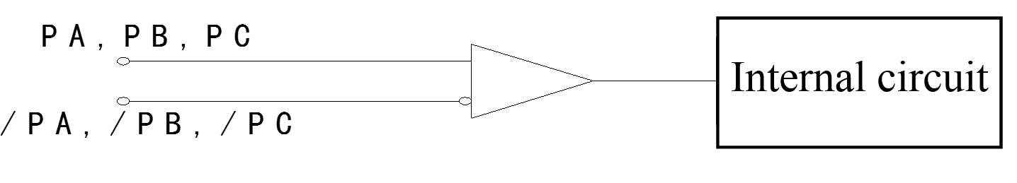
In the current version, ESC-DAC Board only supports incremental differential signal encoder. The encoder outputs 3 kinds of differential signals, they are phase A, phase Band phase Z. Internal interfaces are using high-speed differential signal receiver, as shown below:
The working electrical level:
|
Differential level(Vid=VPA-V/PA) |
State |
|
Vid>0.2V |
Logic'1 ' |
|
-0.2V<Vid<0.2V |
Uncertain |
|
Vid<-0.2V |
Logic'0 ' |
The basic parameters:
|
Maximum common mode voltage |
±10V |
|
Maximum differential mode voltage |
|
|
Maximum speed |
32Mbps |
|
Recommended working electrical level |
0-5V |
3.2.6.6 Principles of Safety Relay EMG Interface
Safety relay interface is used in the situation of an accident or system failure, and all movements of the device settings should be stopped manually. This function in the Board is completely realized by the hardware, so it is totally independent of programmable devices and can improve the safety and reliability of the system. An emergency stop button with normally closed contact is necessary in the system, and the JM4 jumper should be disconnected internal the board when this function is used. The schematic diagram and recommended wiring is as follows:
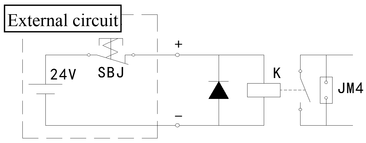
In the figure above, the internal relay K is the kind of 24V relay, and working current is about 8mA. Although there is no need to distinguish between positive and negative poles of the relay itself, the current of the external power supply must flows in from the '+' terminal and flows out from the '-' terminal because of the presence of free-wheeling diode. This relay K and the relay described in chapter 6.4 are the same relay, and the associated circuit of the contact side can be referred to chapter 6.4.
3.2.6.7 Principles of BRK brake Interface
Brake signal is used when the servo motor is not working, and the shaft is locked by an external mechanical device, by using this method the accident caused by servo motor is still rotating (because of the vibration and other reasons of the other devices in the system) can be avoided.( Please refer to the relevant manuals to make sure that whether the servo motor contains braking mechanism or not.) Usually brake signals of the servo motor are sent by servo controller, so the braking interface is not needed. Brake interface is set in the ESC-DAC board for the convenience of users and tidy of the cables and it can be used when needed. There are four servo interfaces in the DAC board, and there is a BRK brake interface in each servo interface. The schematic diagram is as follows:

As it shows in the figure above, braking control signals of each servo interface is controlled by the DI2 pin, and it should be noted that the DI2 signal is a kind of internal signal processed via the interface circuit, therefore it is labeled "DI2 ’". According to the chapter 6.3, board internal logic and external logic signal is opposite of the Board, so in the schematic diagram it is the logic '0' that enables brake signal, corresponding to external electrical circuit is that logic '1 'or closed external switch can enable brake signal.
As the final interface output is optocoupler solid state relay, there is no positive and negative points in principle and the identified plus or minus is just for reference. For consistency, it is recommended that the current flows in from pole '+' and flows out from pole '-'. Generally the working current of brake mechanism is large, so it is commonly that let the Board drive intermediate relay first, and then drive the brake mechanism. As it shows in the figure above, KR relay should be used with the external DC power. Even though it has protection circuit inside the Board Interface, it is recommended that freewheeling diode can be added when the condition permits.
In the interface the optocoupler can provide 50mA operating current. And the maximum current is 75mA, but it can not work for a long time. The interface has no current-limiting measures, so it could lead to a shorter life of the optocoupler solid state relay if the operating current exceeds the allowed limit. It should be noted when select the proper relay if this brake relay needs to work for long-term. It is recommended that chose 24V/35mA or other relays with lower operating currents, and operating voltage and operating current should be as small as possible.
Attention: Because shielded cable is not used for this signal cable, the signal is susceptible to disturbed by the power cable. This cable should be arranged far away from the primary cable for reliable operation of the motor.
3.2.6.8 Wring example of DAC Board and the Types of Cables
Wiring example for lathe
Fifure 3.7 Wiring example of the DAC Board for lathe
Wiring example for milling machine
 Figure 3.8 Wiring example of the DAC Board for milling machine
