1.1 All-analog control

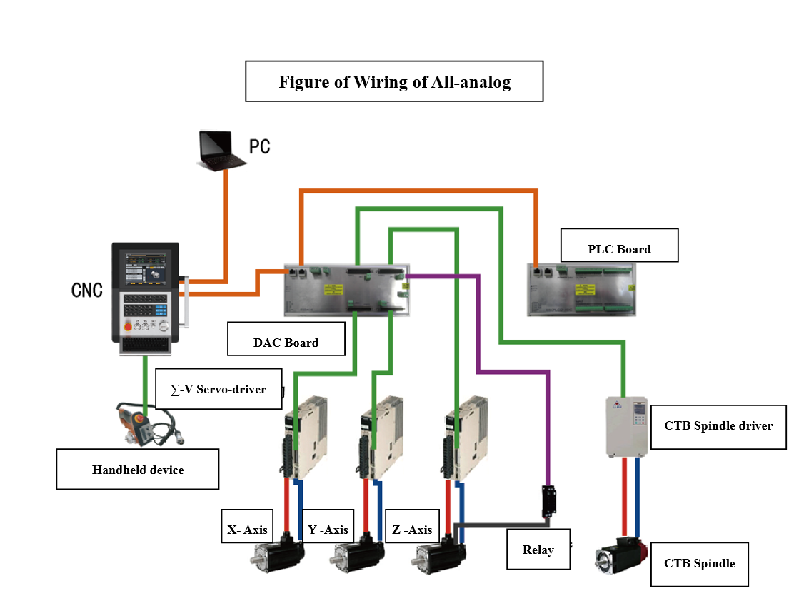
                                                                                                        Figure 1.1 Wiring of All-analog control

Cables:

1. yellow ones for data cables

2. green ones for control cables

3. black ones for braking cables

4. red ones for power cables

5. blue ones for encoder cables

0 (0)
Article Rating (No Votes)
Rate this article
Attachments
There are no attachments for this article.
Comments
There are no comments for this article. Be the first to post a comment.
Full Name
Email Address
Security Code Security Code
Related Articles RSS Feed
1.3 All-digital control
Viewed 2108 times since Wed, Aug 24, 2016
2.3 Installation of PLC Board
Viewed 1674 times since Wed, Aug 24, 2016
3.4 Interface definitions and wiring of Driver
Viewed 31599 times since Wed, Aug 24, 2016
3.3 Definitions and Wring of PLC Board Interface
Viewed 11710 times since Wed, Aug 24, 2016
2.2 Installation of DAC Board
Viewed 1597 times since Wed, Aug 24, 2016
1. i5 System Brief description
Viewed 2083 times since Wed, Aug 24, 2016
3.2 Definitions and Wiring of DAC Board Interface
Viewed 38002 times since Wed, Aug 24, 2016
2.4 Installation of Driver, Motor and Accessories
Viewed 3770 times since Wed, Aug 24, 2016
1.2 Analog spindle & Digital servo-control
Viewed 2793 times since Wed, Aug 24, 2016
2.1 Installation of CNC BOX
Viewed 3293 times since Wed, Aug 24, 2016