

3.4 Interface definitions and wiring of Driver
3.4.1 Wiring of Yaskawa ∑-V Servo-driver
3.4.1.1 System Structure
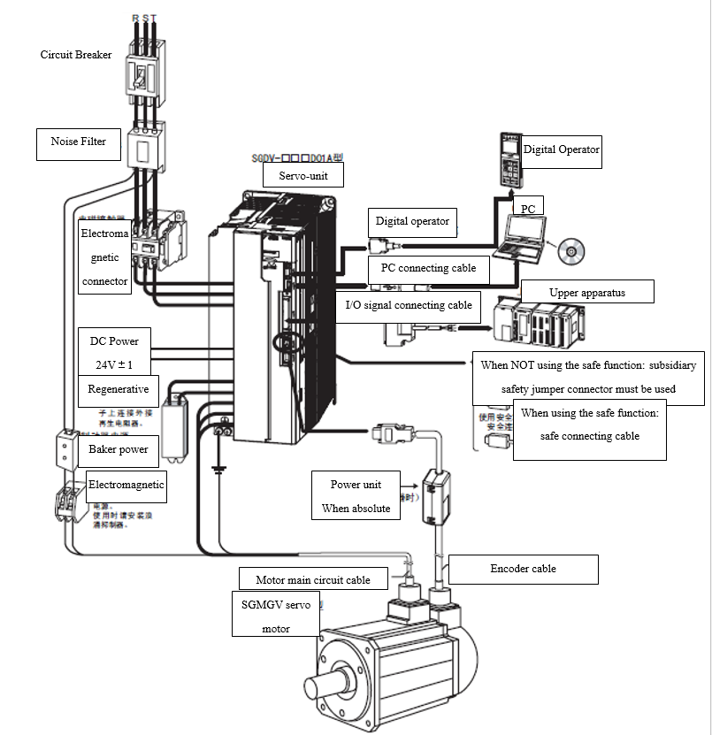
Figure 3.12 Wiring of Yaskawa ∑-V Servo-driver
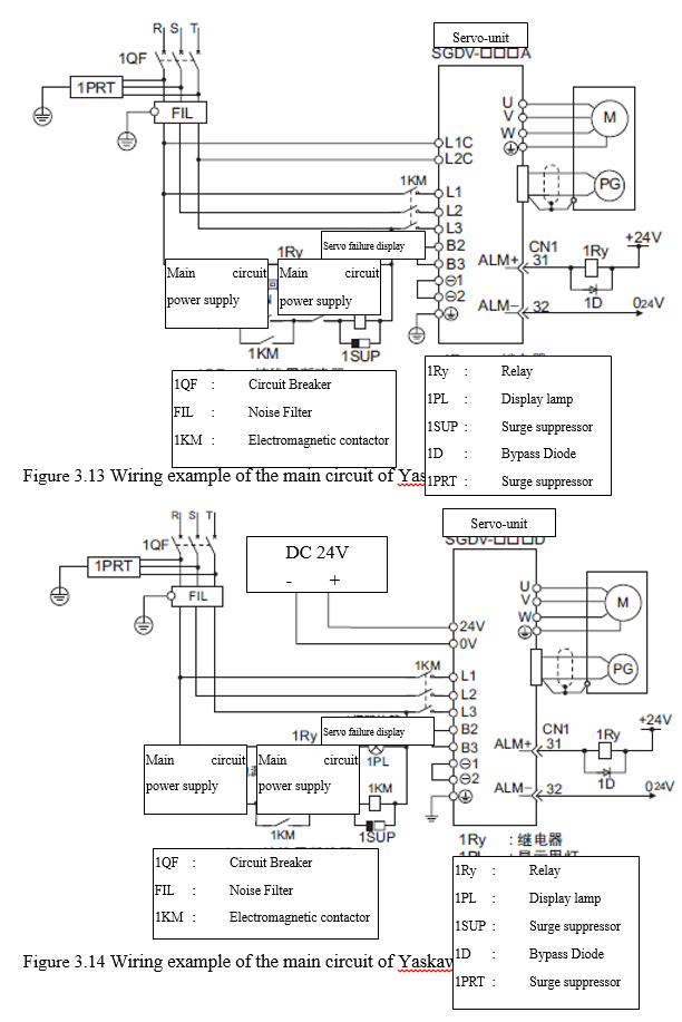
3.4.1.2 Typical wiring example of the main circuit
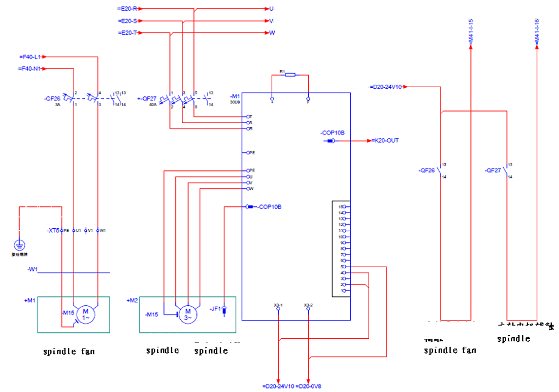
3.4.1.3 Situation of using multiple servo units
The alarm output of each servo unit "ALM" is all connected in series so that the alarm can detect the action from relay "1RY". The output transistor is OFF when the ALM output is in state of alarm. The circuit has a Circuit Breaker "QF" and a noise filter, and they can be used together. It is suggested to choose the proper Circuit Breaker and noise filter that suit for specifications for total power capacity of the multiple servo units (the load condition should be considered).
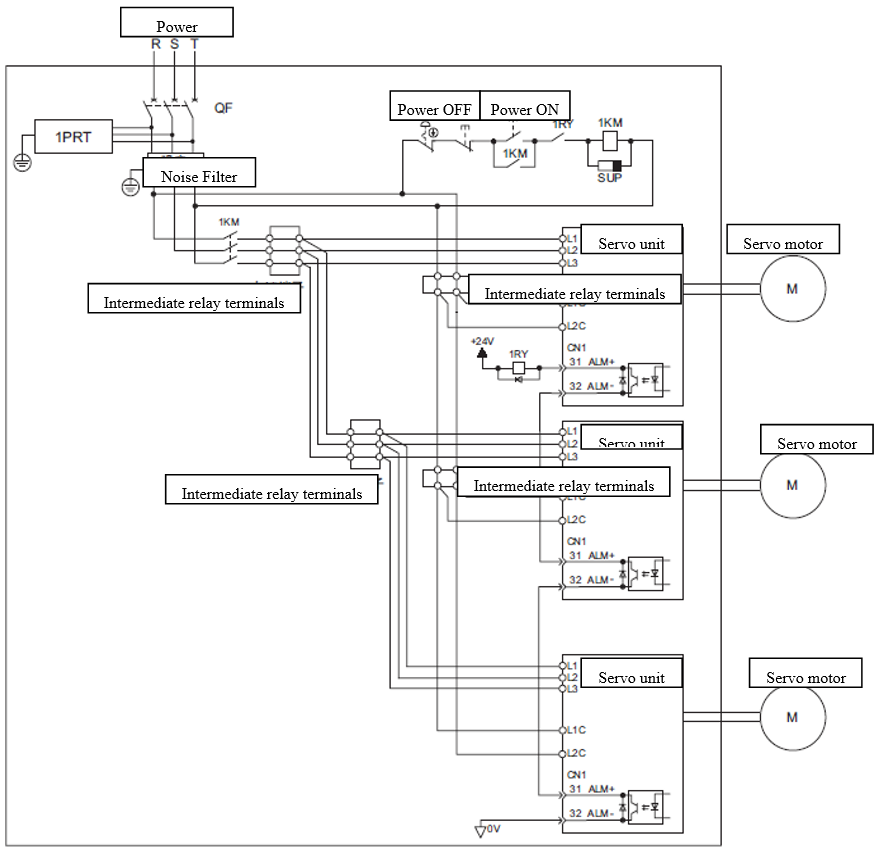
Figure 3.15 Wiring example of multiple servo units
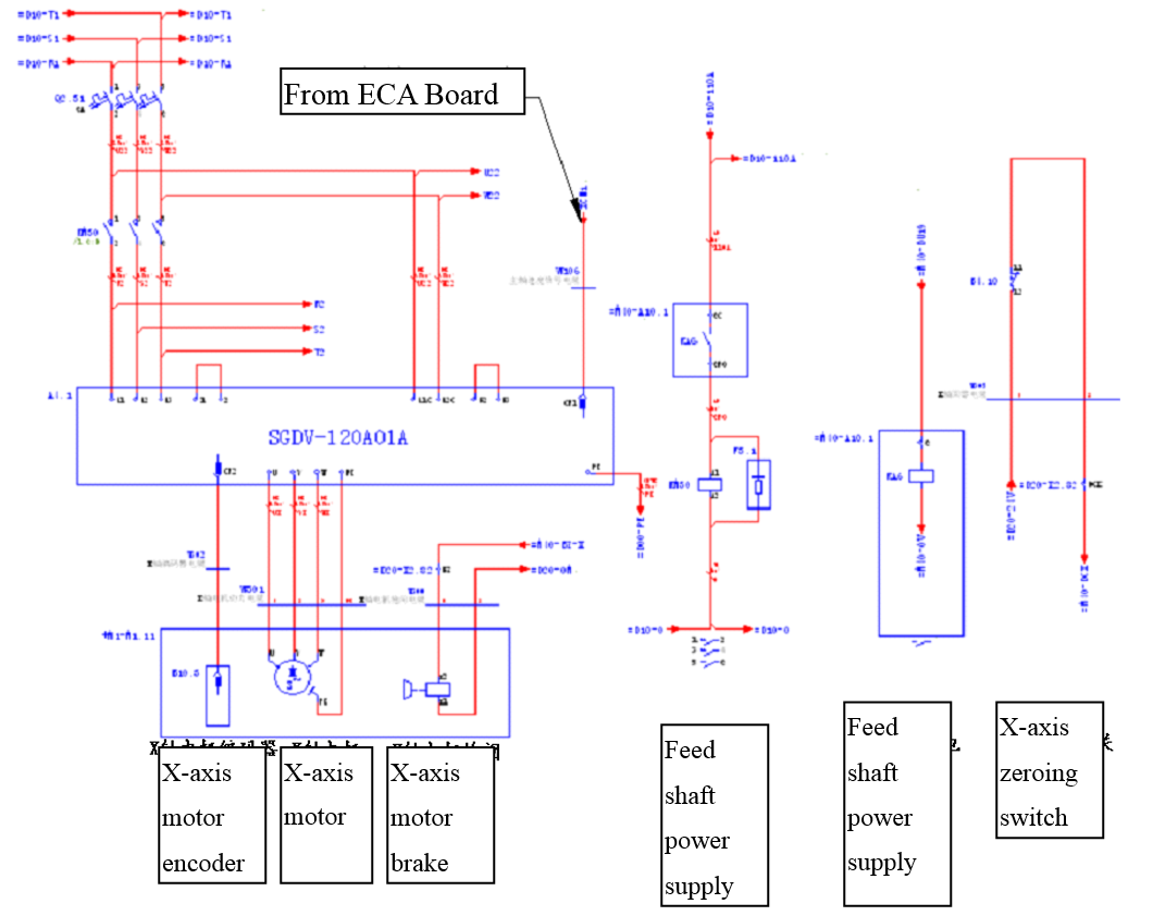
Wiring example
3.4.2 Definitions and Wiring of HSHA servo-driver
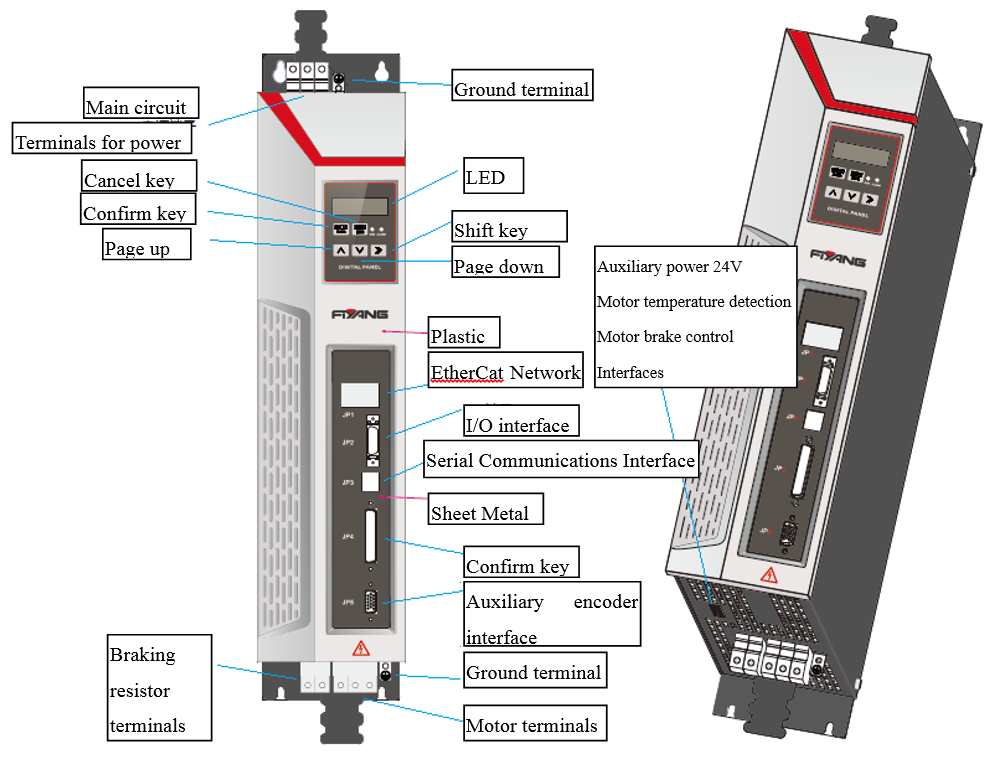
Figure 3.16 HSHA servo-driver
The recommended models of cables
|
Servo-driver model |
Size of the main circuit cable(min) |
Size of the control circuit cable |
Others |
|
HSHA-025-A |
2.5mm2 |
0.75 mm2 |
|
|
HSHA-050-A |
2.5 mm2 |
0.75 mm2 |
|
|
HSHA-075-A |
5 mm2 |
0.75 mm2 |
|
Attention:
1.The size of cable means the size of copper core.
2. The size of ground protecting cable: the cable is recommended to use copper cable and have the size of lager or equal to 6 mm2.
3.4.2.2 Wiring of Main circuit and auxiliary power supply
Overview
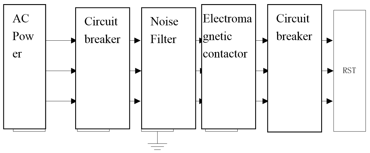
Wiring of the main circuit
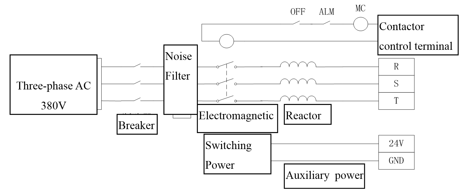
Figure3.18 Wiring of the main circuit
1. Surge absorption device should be added at both ends of the electromagnetic contactor.
2. Voltage range of the main power supply input: Three-phase AC323V ~ AC418V.
3. Voltage range of the auxiliary power supply input:DC24V±10%
Wiring of motor and braking resistor
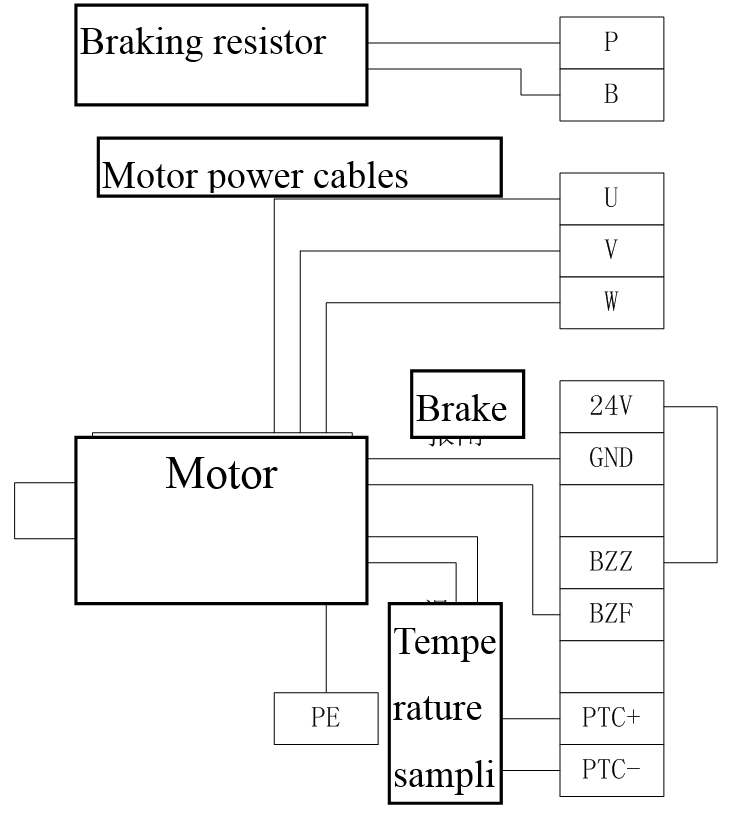
Figure 3.19 Wiring of motor and braking resistor
1. The motor driving cables should be connected correctly to the driver output U, V, W according to the sequence of the servo motor cable phases, and wrong phase sequence will cause the malfunction of the driver.
2. External braking resistor must be connected, and please connect the correct braking resistor in accordance with the recommended values, or it may cause malfunction or damage of the drive.
3. There are no positive or negative poles about the electromagnetic brake (motor brake) control, and the schematic diagram above is just a example for the connection method.
4. It should have at least 30cm space between encoder cables and the motor cables, and between encoder cables and power supply cables.
5. Make sure that the servo driver is well grounded in order to avoid electrical injury.
3.4.2.3 Encoder wiring
Overview
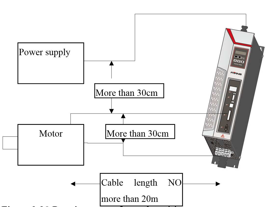
Figure 3.20 Requirements of encoder wiring
1. The length of servo motor cable should be no more than 20m;
2. It should have at least 30cm space between encoder cables and the motor cables, and between encoder cables and power supply cables; do not put them into the same pipeline, and do not band them together.
Servo driver encoder pin arrangement and signal definitions
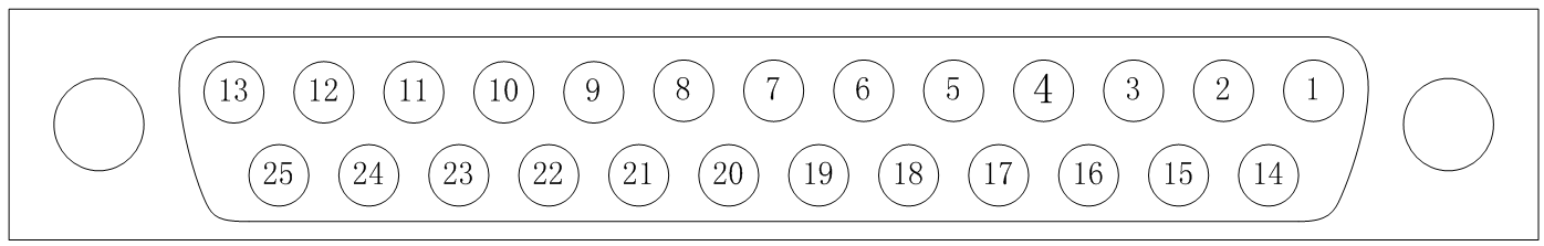
|
Pin number |
1 |
2 |
3 |
4 |
5 |
6 |
7 |
8 |
9 |
|
Definition |
/QEPA |
BAT- |
DATA |
/CLK |
A |
B |
C |
D |
R |
|
Pin number |
10 |
11 |
12 |
13 |
14 |
15 |
16 |
17 |
18 |
|
Definition |
GND |
PTC |
Vcc |
GND-S |
QEPA |
BAT+ |
/DATA |
CLK |
/A |
|
Pin number |
19 |
20 |
21 |
22 |
23 |
24 |
25 |
|
|
|
Definition |
/B |
/C |
/D |
/R |
GND |
PTC- |
Vcc-S |
|
|
Table 3.12 Descriptions of encoder signals definition
|
Symbol |
Pin number |
Name |
Function |
|
/QEPA |
1 |
SSI data |
SSI encoder, data- |
|
QEPA |
14 |
SSI data |
SSI encoder, data+ |
|
BAT- |
2 |
Negative terminal of Battery |
Negative terminal of the encoder backup battery (3.6V battery) |
|
BAT+ |
15 |
Positive terminal of Battery |
Positive terminal of the encoder backup battery (3.6V battery) |
|
DATA |
3 |
Serial Data |
Suitable for Yaskawa encoder, serial data communication, the positive difference. |
|
/DATA |
16 |
Serial Data |
Suitable for Yaskawa encoder, serial data communication, the negative difference. |
|
/CLK |
4 |
SSI clock |
SSI encoder, clock- |
|
CLK |
17 |
SSI clock |
SSI encoder, clock+ |
|
A |
5 |
Phase A of Sine and cosine signal |
Sine and cosine encoder, Phase A, the positive difference. |
|
/A |
18 |
Phase A of Sine and cosine signal |
Sine and cosine encoder, Phase A, the negative difference. |
|
B |
6 |
Phase B of Sine and cosine signal |
Sine and cosine encoder, Phase B, the positive difference. |
|
/B |
19 |
Phase B of Sine and cosine signal |
Sine and cosine encoder, Phase B, the negative difference. |
|
C |
7 |
Phase C of Sine and cosine signal |
Sine and cosine encoder, Phase C, the positive difference. |
|
/C |
20 |
Phase C of Sine and cosine signal |
Sine and cosine encoder, Phase C, the negative difference. |
|
D |
8 |
Phase D of Sine and cosine signal |
Sine and cosine encoder, Phase D, the positive difference. |
|
/D |
21 |
Phase D of Sine and cosine signal |
Sine and cosine encoder, Phase D, the negative difference. |
|
R |
9 |
Phase R of Sine and cosine signal |
Sine and cosine encoder, Phase R, the positive difference. |
|
/R |
22 |
Phase R of Sine and cosine signal |
Sine and cosine encoder, Phase R, the negative difference. |
|
PTC |
11 |
Temperature detection |
Motor built thermistor terminal (Regardless of terminal sign) |
|
/PTC |
24 |
Temperature detection |
Motor built thermistor terminal(Regardless of terminal sign) |
|
GND |
10,23 |
Encoder ground |
Ground of encoder power supply |
|
Vcc |
12 |
Encoder power |
Encoder power supply. |
|
GND-S |
13 |
Ground electrical level feedback |
Feedback of encoder ground level, if there is no feedback from encoder; this pin must be shorted to Pin10 or Pin23. |
|
Vcc-S |
25 |
Power feedback |
Power supply voltage feedback of encoder ground,if there is no feedback from encoder; This pin must be shorted to Pin10 or Pin12. |
3.4.2.4 Input and output signal wiring
Overview
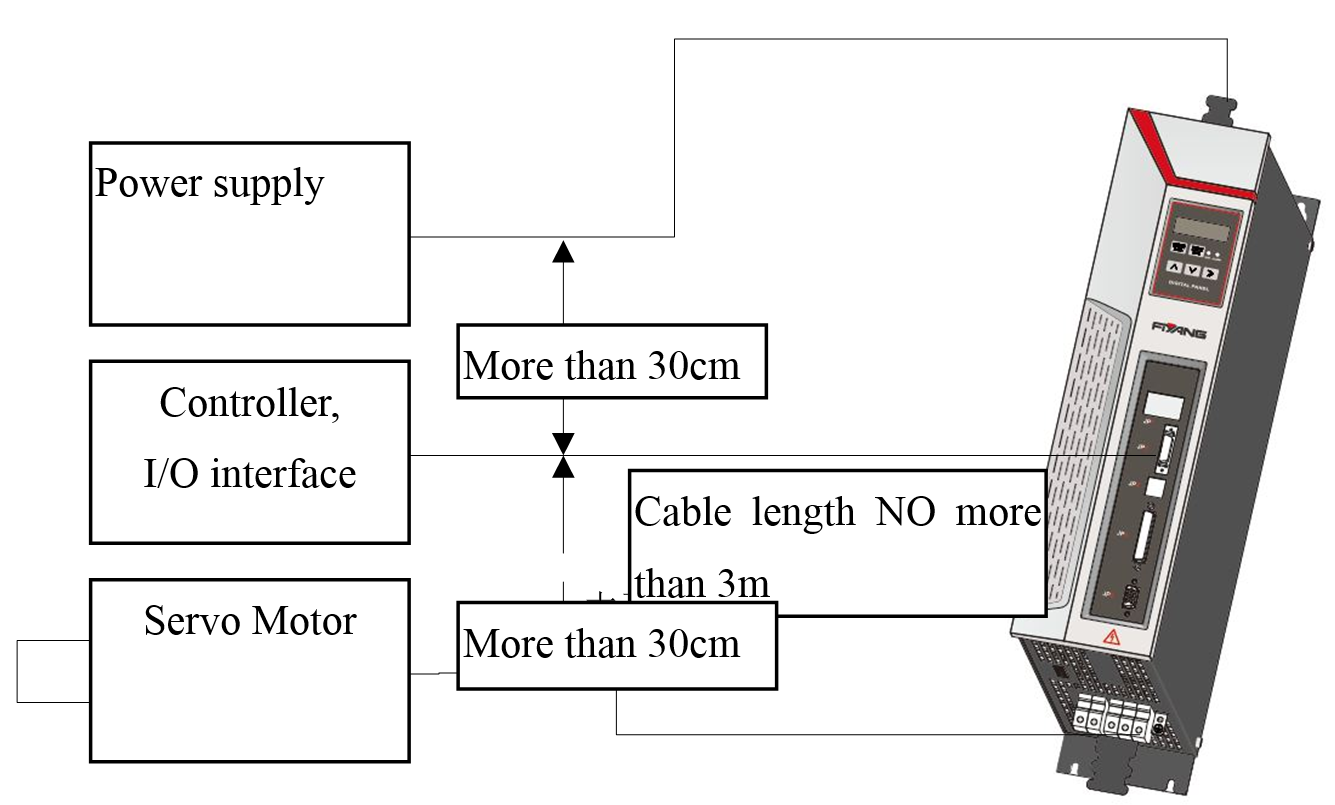
Figure 3.21Wiring Requirements of I/O Signal
1. The space between peripheral devices such as controllers and the servo-driver should be no more than
2. It should have at least 30cm space between the control cables and the power cables, and between the control cables and motor cables; do not put them into the same pipeline or band them together.
3. External 24V DC power supply is used for IO, and the capacity should be lager than 250mA.
4. The load on the switch input and output terminals should be NOT lager than 25V or lager than 50mA.
5. It is necessary that parallel freewheeling diode at the both ends of the load, when switch output signal directly drive inductive loads such as relays.
The output signal circuit wiring
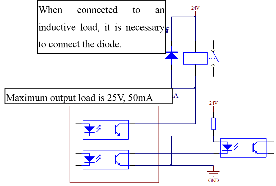
Figure 3.22 The output signal circuit wiring
1. There are four digital outputs as shown above, and the circuit can be set into structure of open collector output. It can be used to drive relay or optocoupler load, and the loading capacity are as shown in figure.
2. When connected to an inductive load such as relay coil, wheeling diode relay must be installed as shown in figure, or the driver will be damaged.
Wiring of switch value signal input circuit
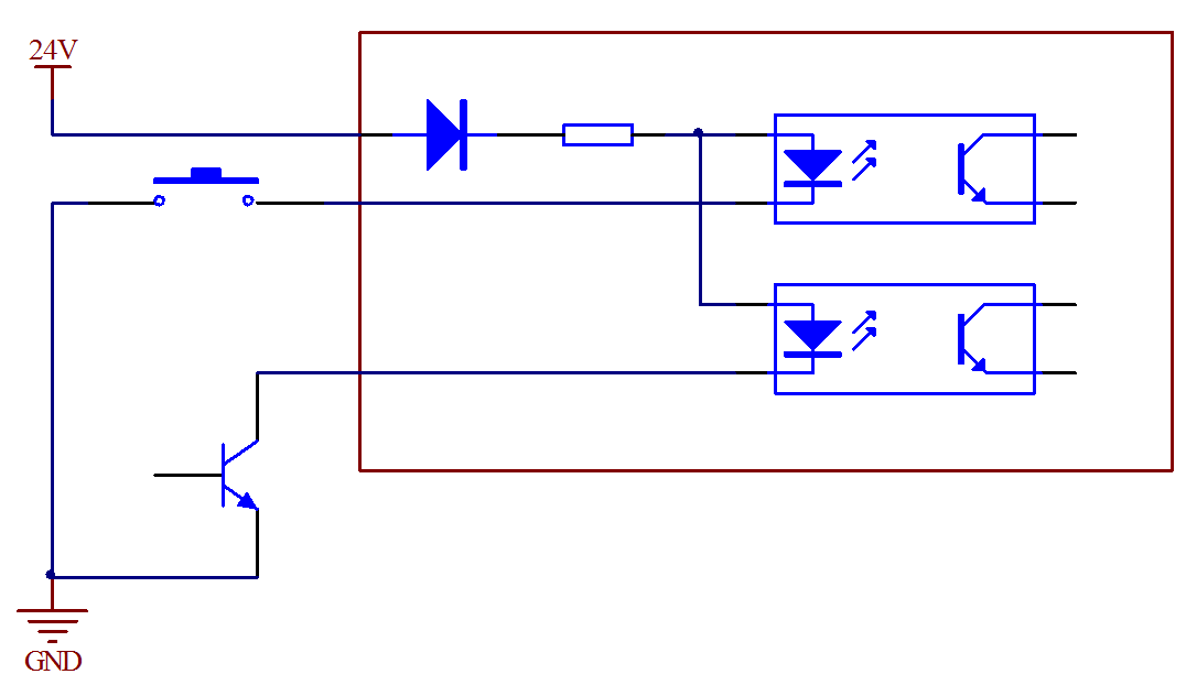
Figure 3.23 Input signal wiring
Switch value signal input circuit can be set in the way of mechanical switch or the way of open-collector of transistor as shown above.
IO Interface (J2 port) pin arrangement and signal definitions
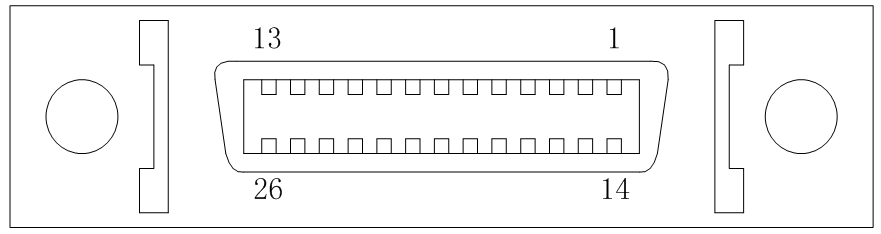
J2 port
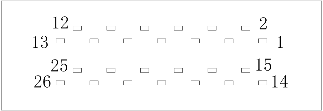
J2 male back connection port
Table 3.13 Pin definitions of J2 port
|
Pin Number |
Definition |
Name |
Input/Output |
|
1、14 |
24V Output+ |
24V |
External power supply |
|
5 |
Enable |
SON |
Input |
|
6 |
Positive Limit |
CWL |
Input |
|
7 |
Negative limit |
CCWL |
Input |
|
8 |
Zero set switch |
HOME |
Input |
|
9、22 |
GND |
GND |
External power ground |
|
10 |
Undefined |
|
|
|
11 |
Undefined |
|
|
|
12 |
Servo is in normal state |
SRDY+ |
Output |
|
13 |
Alarm |
ALM+ |
Output |
|
18 |
The serial Burn-process |
SCI-PG |
Input |
|
19 |
Startup Mode |
Pi-Pe |
Input |
|
20 |
Speed setting select(M) |
SPD1 |
Input |
|
21 |
Speed setting select(L) |
SPD0 |
Input |
|
23 |
Servo is in normal state |
SRDY- |
Output |
|
24 |
Undefined |
|
|
|
25 |
Alarm |
ALM- |
Output |
|
26 |
Undefined |
|
|
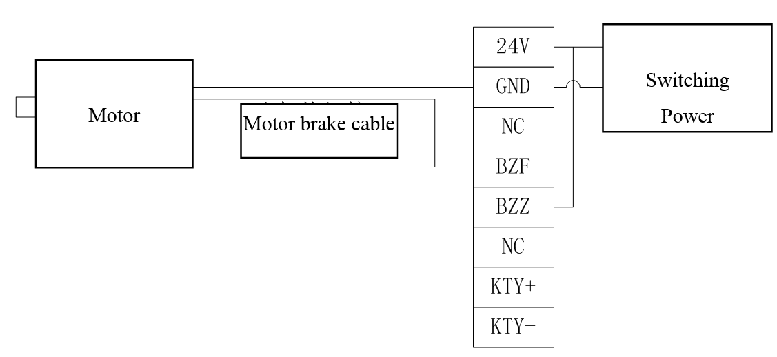
3.4.2.5 Electromagnetic brake wiring
|
Pin Number |
1 |
2 |
3 |
4 |
5 |
6 |
7 |
8 |
|
Definition |
24V |
GND |
NC |
BZF |
BZZ |
NC |
KTY |
KTY- |
3.4.2.6 Example of standard wiring
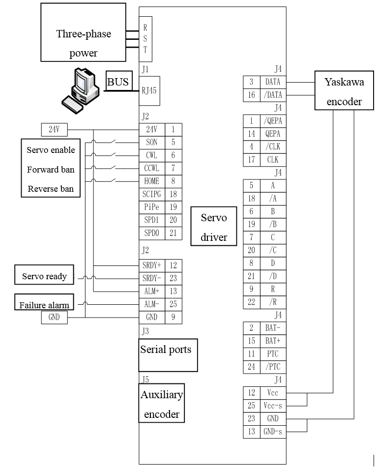
Figure 3.24 HSHA Servo-driver wiring
Before switching on the power, make sure the following is checked:
1、Wiring
1)Servo-driver power (R, S, T) must be correctly connected;
2)Output phases of Servo-driver (U, V, W) must match the servo motor cables phases;
3)There is no shorting connection between output of Servo-driver (U, V, W)and the input power (R, S, T);
4)All wirings must meet the standards of wiring shown in chapter 5.1.1;
5)Make sure the enable terminal (SON) of external servo is set to state OFF;
6)Servo-drivers and servo motor must be well grounded;
7)Voltage applied to J2 port can not exceed DC24V;
8)Stress that applied to the cables should be within the specified range.
2、Environment
There are no wires, metal chips and the other things that could cause the signal lines and power lines shorted in the environment.
3、The mechanical part
Do not let the motor running under the condition of negative load. The so-called negative load is that the torque direction of the motor output is opposite to the running direction of the motor.
Checking all above are correct before the power is switched on.
Attention:
Do not have direct contact with electrical lines terminals, after the main circuit power supply is turned on, even when the servo is not turned on, because it may cause electric shock.
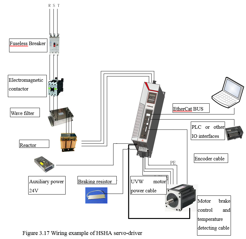
3.4.2.7 Wiring example of HSHA Driver
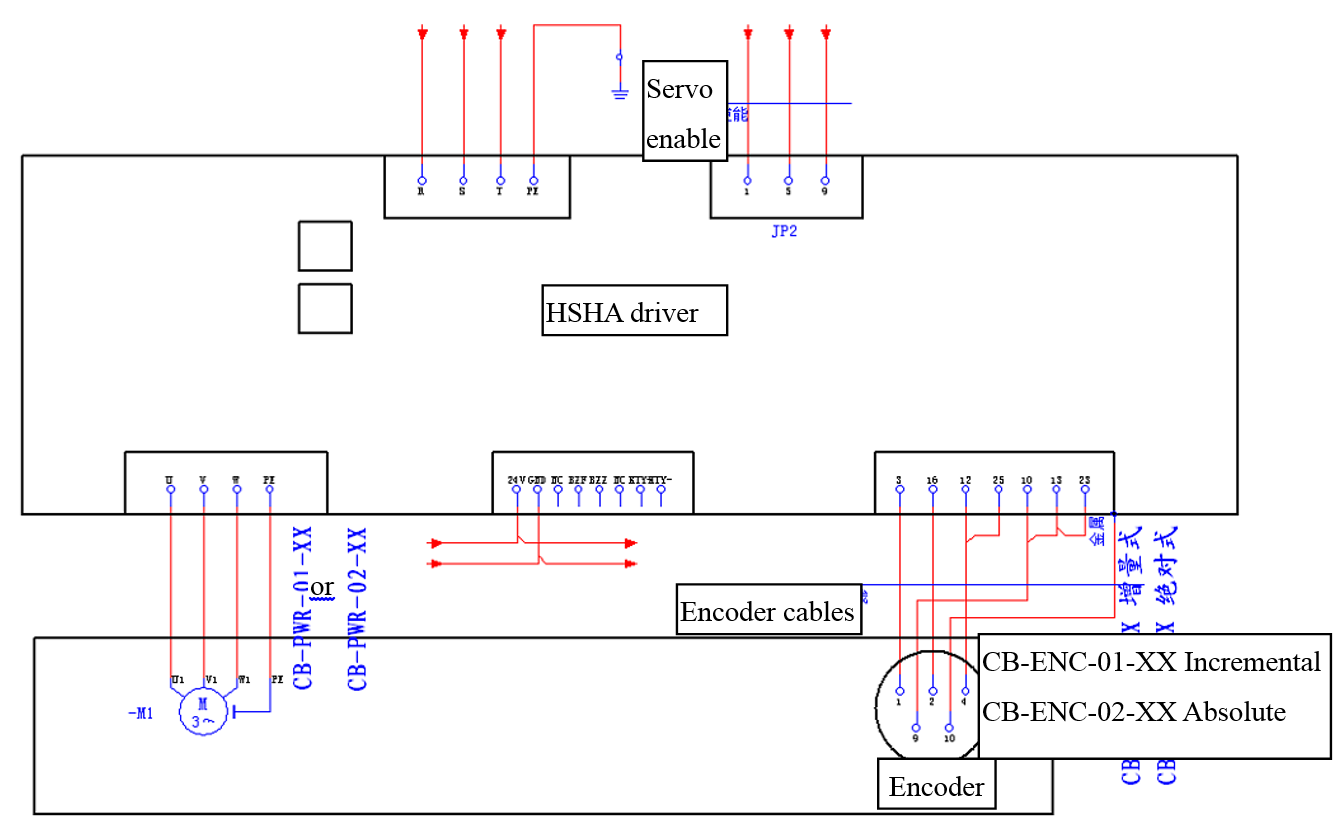
Figure 3.25 Wiring example of HSHA Driver
3.4.3 CTB Spindle driver
3.4.3.1 Overview
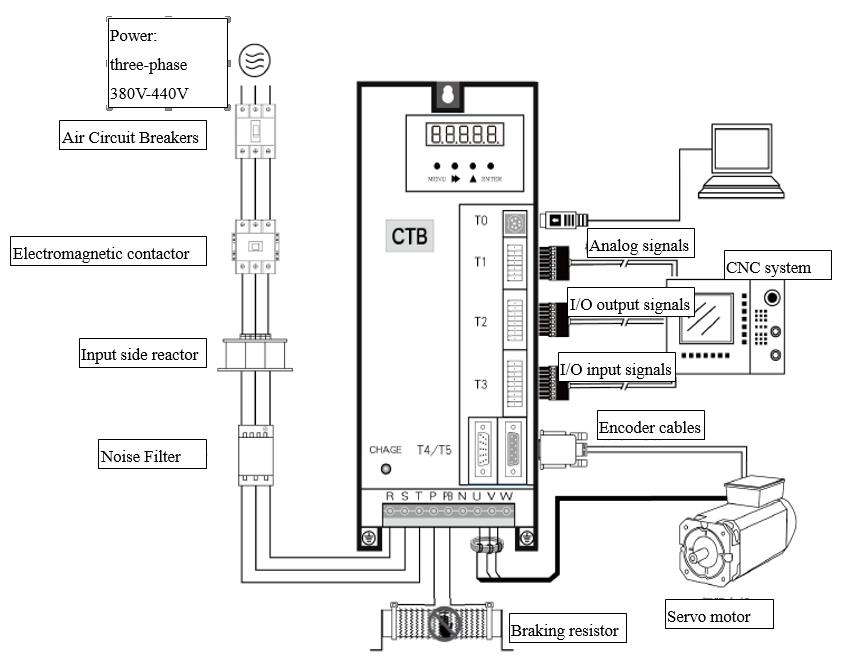
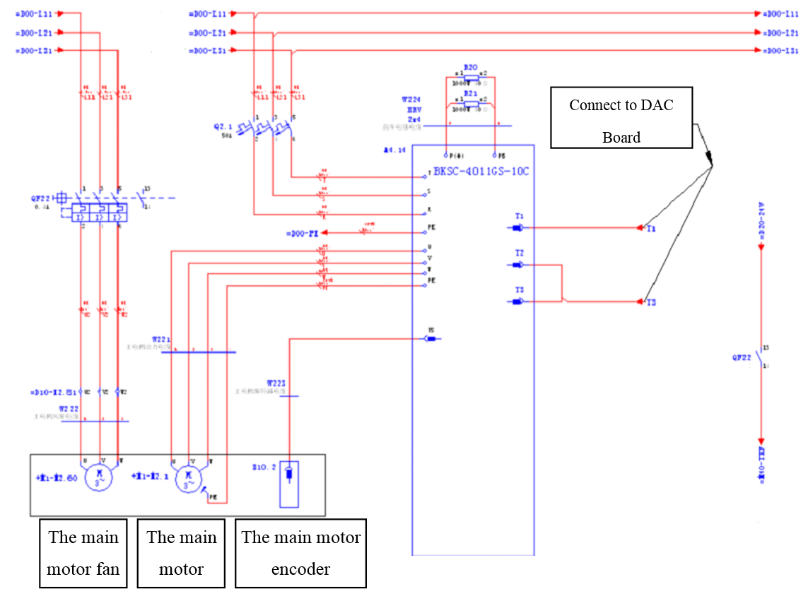
Figure 3.26 Wiring of CTB Spindle
Note:In practical application, the analog signal and the I/O input and output signals that connected to the CNC are in one cable and they are connected in the same port.
3.4.3.2 Connections of the main circuit ports

Figure 3.27 The main circuit ports
Table 3.14 Descriptions and Functions of The main circuit ports
|
Name |
Functions |
Attentions |
|
R S T |
Three-phase AC input terminal 380~440V 50/60Hz |
Protective circuit breaker is needed. |
|
P P1 |
Positive electrode of DC power |
P and N are used for connecting external Brake unit or DC power input |
|
P2 |
DC reactor terminal |
P1 and P2 are used for connecting external DC reactor |
|
PB |
Braking resistor terminal |
P,P2 and PB are used for connecting external Braking resistor |
|
N |
Negative electrode of DC power |
N and P are used for connecting external Brake unit or DC power input |
|
U V W |
Driver output terminal |
Be consistent with the phase sequence of motor when wiring |
|
E |
Ground terminal |
Grounding in mode C, and Grounding resistor value≤4Ω |
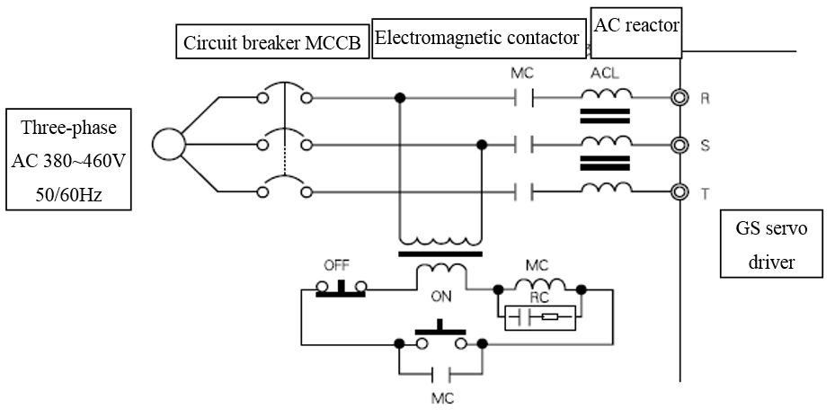
Figure 3.28 Wiring example of the input side of the main circuit
3.4.3.3 Related introduction of the Interfaces
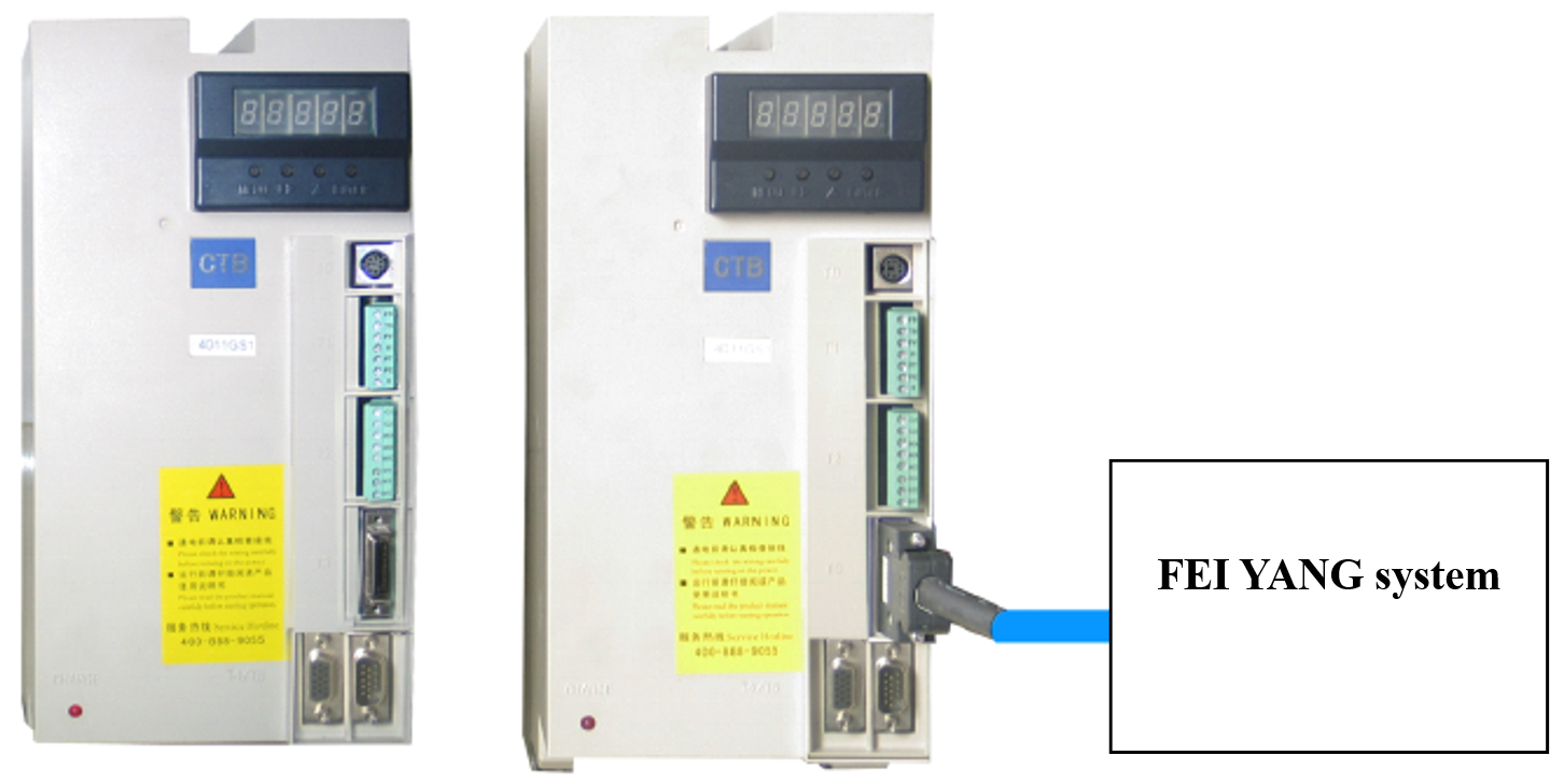
GS driver is connected to the system by using high density plug, and the system analog signals, the output I / O interface singals and the encoder feedback command are combined together.
Example of the signal cable connection

Description of the signal function
|
TYPE |
PIN Number |
Functions |
|
|
Control signal input |
1 |
I1 |
Operation signal. ON: the motor is running, the speed and direction are under -10V ~ 10V analog control; OFF: The motor does not turn. If the signal is changed from ON to OFF when motor speed is not 0, the motor stops at the normal acceleration. |
|
2 |
I2 |
Zero speed servo function. ON: Motor is at zero speed and locked. |
|
|
3 |
I3 |
Exact stop. ON: begin and remain at this state; OFF: exact stop cancelled. |
|
|
4 |
I4 |
Reserved |
|
|
5 |
I5 |
External fault emergency stop. ON: motor is stopped at the maximum acceleration, Stop power supply when the motor is stop. |
|
|
6 |
I6 |
Spindle swing signal. ON: motor swings at the setting torque and frequency. |
|
|
7 |
ST |
Enable Control. |
|
|
8 |
RST |
Pulse input is greater than 100ms, reset the driver. |
|
|
Power Input |
9 |
SV |
External input power +24 V |
|
Analog Input |
16 |
FV |
-10V ~ +10 V analog input, the input impedance: 20KΩ |
|
15 |
SC |
Analog input and digital input common interface |
|
|
Control signal output |
21 |
M0A |
Reserved, Relay type Output. |
|
14 |
M1A |
Driver ready output, relay type output. |
|
|
18 |
M2A |
Exact stop (in place) output, relay type output. |
|
|
17 |
M3A |
Driver fault output, relay type output. |
|
|
19 |
MC |
Relay output common interface |
|
|
Encoder Output |
22 |
OA+ |
A phase of Encoder output. |
|
23 |
OA- |
||
|
25 |
OB+ |
B phase of Encoder output. |
|
|
20 |
OB- |
||
|
24 |
OZ+ |
Z phase of Encoder output. |
|
|
26 |
OZ- |
||
Wiring example
3.4.4 TDE Spindle driver
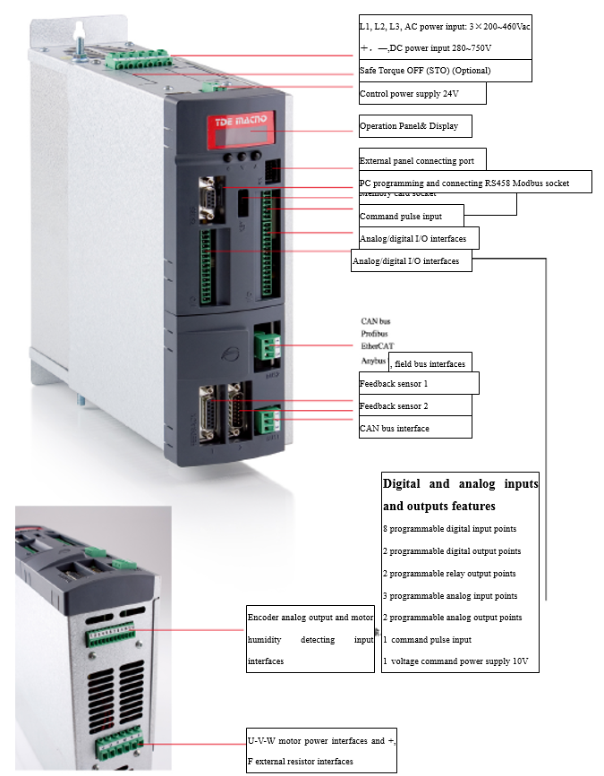
Figure 3.29 TDE Spindle driver
Wiring example
Attention:
All the informations in this manual about CTB, Yaskawa, TDE are extracted from the corresponding product manuals, these informations are for reference only. For more information, please consult the relevant product manuals.
