

3.5 Tool radius compensation G40/G41/G42
3.5.1 Tool radius compensation step

Fig.3.3 Tool radius compensation
As shown in Fig.3.3, tool radius compensation is divided into three steps::
1. Tool compensation creation(start)
The tool approaches the workpiece from the starting point. Base on the programmed path, the tool center offset a certain distance to the left (G41) or to the right (G42).
2. Tool compensationon going
Tool center path offset a certain distance to pragram path.
3. Cutter compensationcancel
Retract, end point of the tool center path coincides with the programmed path.
3.5.2 Instruction format
G41 / G42 activate tool tip radius compensation.
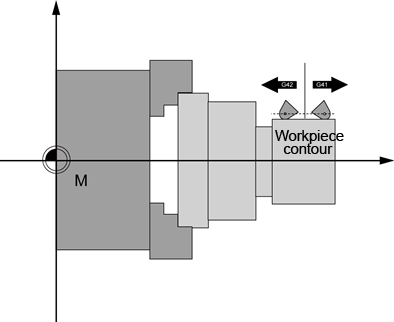
Fig.3.4 Tool tip radius compensation
1. G41 X… Z… ; Tool radius compensation left of contour
2. G42 X… Z… ; Tool radius compensation right of contour
The selection can only be made for linear interpolation (G0, G1).

Fig.3.5 Start of the tool radius compensation

Fig.3.6 End of the tool radius compensation
3. Tool radius compensation OFF: G40
The compensation mode can only be deselected with linear interpolation (G0, G1).
3.5.3 Interference detection
Tool center path after offset appears intersection in non-adjacent segment, that occurs interference. If the tool is operated absolutely along the trace, overcut must occur.
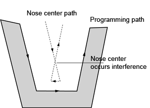
Fig.3.7 overcut
The system has a certain fault tolerance, in some case it can automatically eliminate interference and generate a new track of machining; when interference can not be eliminated the system alarms an error and aborts.
Note
1. Whentool compensationis active,you can not program with the following instructions:
1)G17/G18/G19;
2)G33;
3)G53~G59,G500/G501;
4)During theexecution oftool compensation, you can notchange the toolandtool compensation number.
2. The G41 ⇄ G42 compensation direction can be changed without writing G40 in between.
3. The compensation mode can only be took effect or deselected with G00, G01.
