

3.3 Tool offset table
Article Number: 504 | Rating: 5/5 from 1 votes | Last Updated: Fri, Aug 26, 2016 9:12 AM
Tool information:
1. Name: tool name
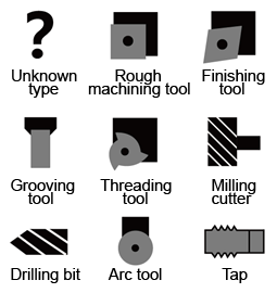
2. Type:
3. Tool group: tool group number;
4. Cutting edge number: 1-9, for different tool types, the cutting edge positions are different, so is the radius.
Standard information:
1. L1_X: X direction length compensation value (radius value);
2. L2_Z: Z direction length compensation value;
3. Radius: the tool tip radius value.
Extended Information:
1. Wear L1_X: X direction length wear value (diameter value);
2. Wear L2_Z: Z direction length wear value;
3. Wear radius: radius wear value.
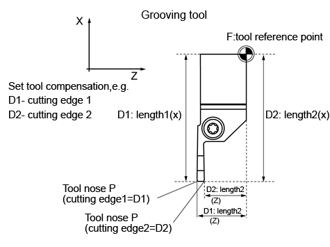
Fig.3.1 Tool length compensation values
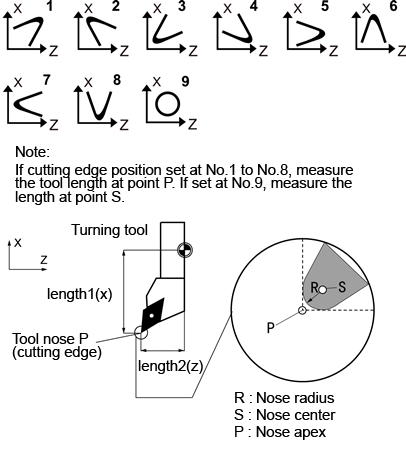
Fig.3.2 Cutting edge position
