1.1 Coordinate systems

For machine tools, right−handed, right−angled coordinate systems are used, as shown in Fig.1.1. The movements on the machine are described as a relative movement between tool and workpiece.

                                                                                            Fig.1.1 Coordinate systems

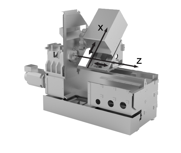
                                                                  Fig.1.2 Coordinate system of a turning machine

Coordinate system of a turning machine is shown as Fig.1.2. The origin of the coordinate system is the machine zero, Z-axis coincides with the spindle center axis, the positive direction is away from the spindle face; X-axis perpendicular to the spindle axis, the positive direction is away from the spindle center.

Common lathe system coordinate system is defined as follows:

1. Machine coordinate system MCS: The origin of the coordinate system is the machine zero. This point only represents a reference point defined by the machine manufacturer. Machine determine the MCS by returning the referencepoint.

2. Workpiece coordinate system WCS: The coordinate system is used to describe the geometry of a workpiece in the workpiece program. The workpiece zero can be freely selected by the programmer in the Z axis. In the X axis, it lies in the turning center.

0 (0)
Article Rating (No Votes)
Rate this article
Attachments
There are no attachments for this article.
Comments
There are no comments for this article. Be the first to post a comment.
Full Name
Email Address
Security Code Security Code
Related Articles RSS Feed
2.2 Dimensions in metric units and inches: G70/G71
Viewed 2039 times since Thu, Aug 25, 2016
3.3 Tool offset table
Viewed 3903 times since Fri, Aug 26, 2016
5.3.2 Undercut CYCLE94
Viewed 3560 times since Fri, Aug 26, 2016
1.3 Subroutine
Viewed 2112 times since Thu, Aug 25, 2016
5.2.4 Rigid tapping CYCLE84
Viewed 3088 times since Fri, Aug 26, 2016
5.2.8 Drilling with stop 2 (boring 4) CYCLE88
Viewed 1790 times since Fri, Aug 26, 2016
1.4 Program jumps
Viewed 25551 times since Thu, Aug 25, 2016
3.5 Tool radius compensation G40/G41/G42
Viewed 5584 times since Fri, Aug 26, 2016
2.1 Absolute / incremental dimensioning: G90/G91, AC/IC
Viewed 4912 times since Thu, Aug 25, 2016
5.1 Overview of cycles
Viewed 1716 times since Fri, Aug 26, 2016