

5.3.1 Groove CYCLE93
Programming:
CYCLE93(AXFA, AXSA, WIDG, DEPG, ANGC, ANG1, ANG2, RCO1, RCO2, RCI1, RCI2, FAL1, FAL2, IDEP, DWT, TYP, VRT)
Parameters:
|
AXFA |
Real |
Starting point in the transverse axis (radius value input) |
|
AXSA |
Real |
Starting point in the longitudinal axis (absolute) |
|
WIDG |
Real |
Groove width (enter without sign |
|
DEPG |
Real |
Groove depth (enter without sign, radius value input) |
|
ANGC |
Real |
Angle between contour and longitudinal axis Range of values: 0<= ANGC <=180 degrees |
|
ANG1 |
Real |
Flank angle 1: on the side of the groove determined by the starting point (enter without sign) Range of values: 0<=ANG1<89.999 degrees |
|
ANG2 |
Real |
Flank angle 2: on the other side (enter without sign) Range of values: 0<=ANG2<89.999 |
|
RCO1 |
Real |
Radius/chamfer 1, externally: on the side determined by the starting point |
|
RCO2 |
Real |
Radius/chamfer 2, externally, on the other side |
|
RCI1 |
Real |
Radius/chamfer 1, internally: on the starting point side |
|
RCI2 |
Real |
Radius/chamfer 2, internally, on the other side |
|
FAL1 |
Real |
Finishing allowance at the recess base (radius value input) |
|
FAL2 |
Real |
Finishing allowance at the flanks (radius value input) |
|
IDEP |
Real |
Infeed depth (enter without sign) |
|
DWT |
Int |
Dwell time at recess base |
|
TYP |
Int |
Machining type, range of values: 1...8 and 11...18 |
|
VRT |
Real |
Variable retraction distance from contour, incremental (enter without sign) |
Function:
The grooving cycle can be used to carry out symmetrical and asymmetrical grooves for longitudinal and face machining at any straight contour elements. External and internal grooves can be produced.
Sequence:
The infeed in the depth (towards the groove base) and in the width (from groove to groove) are calculated in the cycle internally and distributed equally with the maximum possible value. When grooving at oblique faces, the tool will traverse from one groove to the next on the shortest path, i.e. parallel to the cone at which the groove is machined. During this process, a safety clearance to the contour is calculated internally in the cycle.
Step 1: Paraxial roughing down to the base of the groove in single infeed steps. After each infeed, the tool is retracted for chip breaking. (as Fig.5.12);
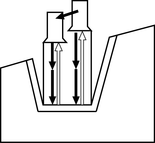
Fig.5.12 Step1 figure
Step 2:as shown in Fig.5.13, The groove is machined vertically to the infeed direction in one or several steps whereby each step, in turn, is divided according to the infeed depth. From the second cut along the groove width onwards, the tool will retract by 1 mm before each retraction.
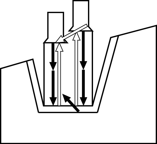
Fig.5.13 Step2 figure
Step 3: Machining of the flanks in one step if angles are programmed under ANG1 or ANG2. Infeed along the groove width is carried out in several steps if the flank width is larger.
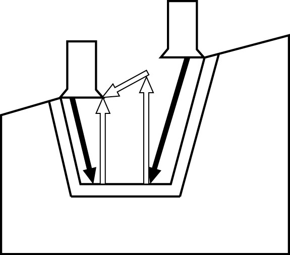
Fig.5.14 Step3 figure
Step 4: Stock removal of the finishing allowance parallel to the contour from the edge to the groove center. During this operation, the tool radius compensation is selected and deselected by the cycle automatically.
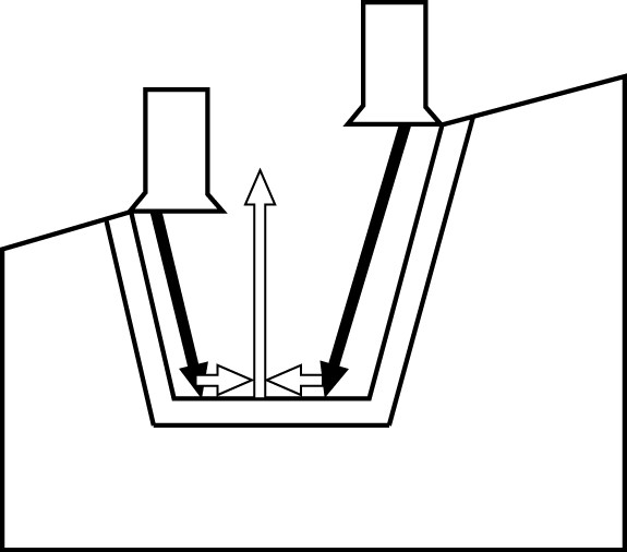
Fig.5.15 Step4 figure
Explanation of parameters:
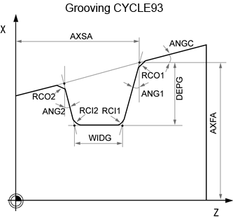
Fig.5.16 Parameter
AXFA and AXSA (Starting point)
The two parameters can be used to define the starting point of the groove. From the starting point, the cycles calculates the contour automatically (as shown in Fig.5.16,Fig.5.17).
1. The cycle determines its own starting point;
2. For an external groove, movement begins in the direction of the longitudinal axis, for an internal groove in the direction of the facing axis.
3. Grooves at bent contour elements can be realized differently. Depending on the form and radius of the bend, either a paraxial straight line can be laid over the maximum of the bend or a tangential oblique line can be created in a point of the edge points of the groove.
4. Radii and chamfers at the groove edge make sense with bent contours only if the appropriate edge point is on the straight line specified for the cycle.
WIDG and DEPG (groove width and groove depth)
The parameters groove width (WIDG) and groove depth (DIAG) are used to define the form of the groove.
1. If the groove width is larger than that of the active tool, the width is removed in several steps. When doing so, the whole width is distributed by the cycle equally. The maximum infeed is 95% of the tool width after deduction of the cutting edge radii. This provides a cutting overlap.
2. If the programmed groove width is smaller than the real tool width, the error message is generated and machining is aborted. The alarm will also appear if a cutting edge width equal to zero is detected in the cycle.

Fig.5.17 Parameter
ANGC (angle)
Use the STA1 parameter to program the angle of the oblique line at which the groove is to be machined. The angle can assume values between 0 and 180 degrees and always refers to the longitudinal axis (as shown in Fig.5.16,Fig.5.17).
ANG1 and ANG2 (flank angle)
As shown in Fig.5.16,Fig.5.17, Asymmetric grooves can be described by flank angles specified separately. The angles can assume values between 0 and 89.999 degrees.
RCO1, RCO2 and RCI1,RCI2(radius/chamfer)
As Fig.5.16, the parameters are used to define the radius/chamfer of the groove. It is imperative to enter the radii with positive sign, and the chamfers with negative sign.
How the programmed chamfers are taken into account is specified in dependence of thetens digit of the TYP parameter.
1. With VARI<10 (tens=0) Chamfers with CHF=...;
2. With VARI>10 chamfers programmed with CHR
(CHF/CHR sees section 2.7.7)
FAL1 and FAL2 (finishing allowance)
It is possible to program separate finishing allowances for groove base and flanks. During roughing, stock removal is carried out up to these finishing allowances. Then a cut is carried out parallel to the contour with the same tool along the final contour.
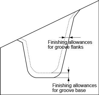
Fig.5.18 Finishing allowance
IDEP (infeed depth)
As Fig.5.17, You can divide the paraxial grooving into several depth infeeds by programming an infeed depth. After each infeed, the tool is retracted by 1 mm for chip breaking. The parameter IDEP must be programmed in all cases.
TYP (machining type)
The machining type of the groove is defined with the units digit of the TYP parameter. The tens digit of parameter TYP determines how the chamfers are taken into account.
1. TYP1..8: The chamfers will be taken into account as CHF.
2. TYP11..18: The chamfers will be taken into account as CHR.

Fig.5.19 Machining type of the groove
If the parameter has a different value, the cycle will abort with alarm. This is not the case if the radii/chamfers come into contact or intersect at the groove base or if you try to carry out a face grooving operation at a contour segment located parallel to the longitudinal axis. In such cases, the cycle will abort with alarm.
VRT (variable retraction path)
The retraction path can be programmed in the VRT parameter on the basis of the outside or inside diameter of the groove. For VRT=0 (parameter not programmed), the tool is retracted by 1 mm. The same retraction path is also used for chip breaking after each depth infeed into the groove.
Note:
1. Before calling the grooving cycle, a double−edged tool must be enabled
2. The offset values for the two cutting edges must be stored in two successive D numbers of the tool whereby the first of which must be activated prior to the first cycle call
3. The cycle itself defines for which machining step it will use which of the two tool compensation values and will also enable them automatically
4. After completion of the cycle, the tool compensation number programmed prior to the cycle call is active again.
Example:
This program is used to produce a groove externally at an oblique line in the longitudinal direction. The starting point is on the right-hand side at X35 Z60. The cycle will use the tool compensations D1 and D2 of tool T5. The cutting tool must be defined accordingly.
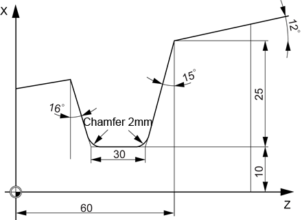
Fig.5.20 Example
|
N10 T5 D1 S400 M03 |
Specification of cutting parameter |
|
N20 G95 G90 F0.2 |
|
|
N30 G00 X80 Z65 |
Approach drilling cycles starting position |
|
N40 CYCLE93(35, 60, 30, 25, 12, 15, 16, 0, 0, -2, -2, 1, 1, 10, 1, 5, 0) |
Cycle call |
|
N50 G00 G90 X50 Z65 |
Next position |
|
N60 M02 |
End of program |
