

5.2.3 Deep-hole drilling CYCLE83
Programming:
CYCLE83 (RTP, RFP, SFD, DEP, RDP, FDEP, FRDP, DAM, DTB, DTS, FRF, TYP)
Parameters:
|
RTP |
Real |
Retraction plane (absolute) |
|
RFP |
Real |
Reference plane (absolute) |
|
SFD |
Real |
Safety clearance (enter without sign) |
|
DEP |
Real |
Final drilling depth (absolute) |
|
RDP |
Real |
Final drilling depth relative to the reference plane (enter without sign) |
|
FDEP |
Real |
First drilling depth (absolute) |
|
FRDP |
Real |
First drilling depth relative to the reference plane (enter without sign) |
|
DAM |
Real |
Amount of degression (enter without sign) |
|
DTB |
Int |
Dwell time at final drilling depth (chip breaking) |
|
DTS |
Real |
Dwell time at starting point and for swarf removal |
|
FRF |
Real |
Feedrate factor for the first drilling depth (enter without sign) Range of values: 0.001 ... 1 |
|
TYP |
Int |
Machining type: Chip breakage=0, Chip removal=1 |
Function:
The tool drills at the programmed spindle speed and feedrate to the entered final drilling depth. Deep hole drilling is performed with a depth infeed of a maximum definable depth executed several times, increasing gradually until the final drilling depth is reached. The drill can either be retracted to the reference plane + safety clearance after every infeed depth for swarf removal or retracted in each case by 1 mm for chip breaking.
Sequence:
Deep-hole drilling with chip removal (TYP=1):
1. Approach of the reference plane brought forward by the safety clearance by using G00
2. Traversing to the first drilling depth with G01, the feedrate for which is derived from the feedrate defined with the program call which is subject to parameter FRF (feedrate factor)
3. Dwell time at final drilling depth (parameter DTB);
4. Retraction to the reference plane brought forward by the safety clearance for swarf removal by using G00
5. Dwell time at the starting point (parameter DTS);
6. Approach of the drilling depth last reached, reduced by anticipation distance by using G00
7. Traversing to the next drilling depth with G01 (sequence of motions is continued until the final drilling depth is reached;
8. Retraction to the retraction plane with G00
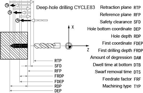
Fig.5.3 CYCLE83 (TYP=1)
Deep-hole drilling with chip breakage(TYP=0):
1. Approach of the reference plane brought forward by the safety clearance by using G00
2. Traversing to the first drilling depth with G1, the feedrate for which is derived from the feedrate defined with the program call which is subject to parameter FRF (feedrate factor);
3. Dwell time at final drilling depth (parameter DTB);
4. Retraction by 1 mm from the current drilling depth with G01 and the feedrate programmed in the calling program (for chip breaking);
5. Traversing to the next drilling depth with G01 and the programmed feedrate (sequence of motions is continued until the final drilling depth is reached);
6. Retraction to the retraction plane with G00
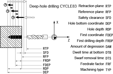
Fig.5.4 CYCLE83 (TYP=0)
Explanation of the parameters:
1. Parameters RTP,RFP,SFD,DEP,RDP, see CYCLE81
2. Parameters DEP(or RDP), FDEP(or DRDP) and DAM:
The intermediate drilling depth are calculated in the cycle on the basis of final drilling depth(DEP or RDP), first drilling depth(FDEP or FRDP) and amount of degression (DAM) as follows:
1)In the first step, the depth parameterized with the first drilling depth is traversedas long as it does not ex ceed the total drilling depth.;
2)From the second drilling depth on, the drilling stroke is obtained by subtracting the amount of degression from the stroke of the last drilling depth, provided that the latter is greater than the programmed amount of degression.
3)The next drilling strokes correspond to the amount of degression, as long as the remaining depth is greater than twice the amount of degression.
4)The last two drilling strokes are divided and traversed equally and are therefore always greater than half of the amount of degression.
3. DTB(dwell time at final drilling depth): The dwell time to the final drilling depth (chip breakage) is programmed under DTB in seconds.
4. DTS(dwell time at the starting point): The dwell time at the starting point is only performed if TYP=1 (chip removal).
5. FRF(feedrate factor): With this parameter, you can enter a reduction factor for the active feedrate which only applies to the approach to the first drilling depth in the cycle.
6. TYP(machining type): If parameter TYP=0 is set, the drill retracts 1 mm after reaching each drilling depth for chip breaking. If TYP=1 (for chip removal), the drill traverses in each case to the reference plane shifted by the amount of the safety clearance.
Example:
The program machines a deep hole with cycle CYCLE83. The drilling axis is always the Z axis. Programming zero point is the center of end face. Dwell time is 1 second.
|
N10 G00 G90 G17 G40 T1 D1 S400 M03 |
Specification of technology values |
|
N20 G95 G01 Z10 X0 F0.2 |
Approach drilling cycles starting position |
|
N30 CYCLE83(10, 0, 1, -20, 20, -5, 5, 1, 1, 1, 1, 1) |
Cycle call |
|
N40 G00 Z10 |
Next position |
|
N50 M02 |
End of program |
