

5.3.2 Undercut CYCLE94
Programming:
CYCLE94 (AXFA, AXSA, FORM)
Parameter:
|
AXFA |
Real |
Starting point in the transversal axis (enter without sign, Diameter value) |
|
AXSA |
Real |
Starting point in the longitudinal axis (absolute) |
|
FORM |
String |
Definition of the form, Values: E (for form E), F (for form F) |
Function:
This cycle can be used to perform undercuts of forms E and F with standard requirements at a finished diameter of >3 mm.
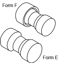
Fig.5.21 Undercut form
Sequence:
Position reached prior to cycle start, the starting position can be any position from which the undercut can be approached without collision. The cycle creates the following sequence of motions:
1. Approach of the starting point determined in the cycle by using G00
2. Selection of the cutter radius compensation according to the active tool point direction and traveling along the undercut contour at the feedrate programmed prior to the cycle call
3. Retraction to the starting point with G00 and deselection of the cutter radius compensation with G40.
Explanation of parameters:
AXFA and AXSA (starting point)
Use the parameter AXFA to specify the finished part diameter for the undercut. The AXSA parameter defines the finished dimension in the longitudinal axis. If a final diameter of <3 mm results for the value programmed for AXFA, the cycle is canceled, and alarm is issued.
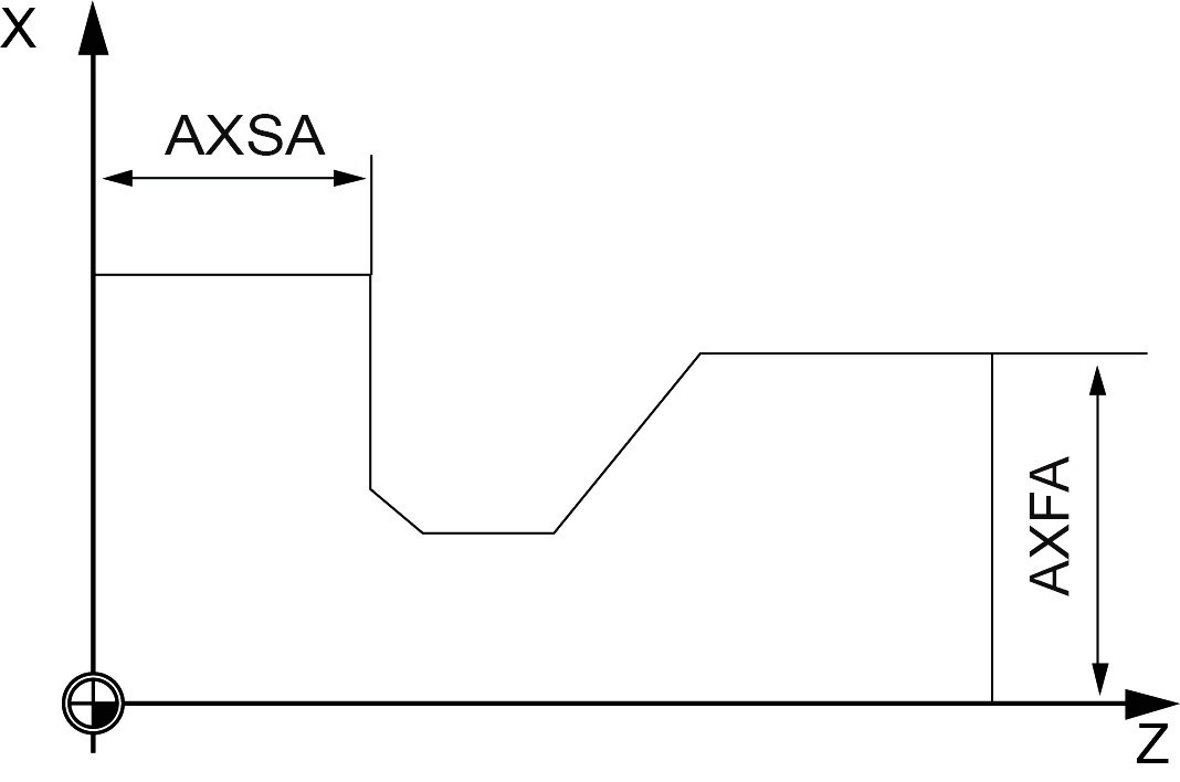
Fig.5.22 Starting point
FORM(definition of form)
Define undercut form (as shown Fig.5.23).
F——Form F E——Form E

Fig.5.23 Undercut form
Explanation:
1. The tool point direction is determined by the cycle automatically from the active tool compensation. The cycle can operate with the tool point directions 1 ... 4. If the cycle detects either of the tool point directions 5 ... 9, the alarm is generated and the cycle is aborted.
2. The cycle determines its starting point automatically. This is by 2 mm away from the end diameter and by 10 mm away from the finishing dimension in the longitudinal axis.
3. The position of this starting point referred to the programmed coordinate values is determined by the tool point direction of the active tool;
4. Before calling the cycle, a tool compensation must be activated, otherwise, the cycle is aborted.
If the value of parameter is not E or F, the cycle aborts and alarm
Example:
This program can be used to program an undercut of form E.
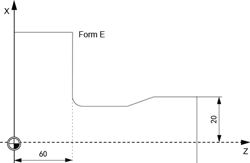
Fig.5.24 Example
|
N10 T1 D1 S300 M03 |
Specification of cutting parameter |
|
N20 G95 F0.3 |
|
|
N30 G00 G90 Z100 X50 |
Approach drilling cycles starting position |
|
N40 CYCLE94 (20, 60, “E”) |
Cycle call |
|
N50 G90 G00 Z100 X50 |
Next position |
|
N60 M02 |
End of program |
