

5.3.3 Rough turning CYCLE95
Programming:
CYCLE95 (NSP, IDEP, FALZ, FALX, FAL, FF1, FF2, FF3, TYP, DWT, DAM, VRT)
Parameters:
|
NSP |
String |
Name of contour subroutine |
|
IDEP |
Real |
Infeed depth (enter without sign, radius input) |
|
FALZ |
Real |
Finishing allowance in the longitudinal axis (enter without sign) |
|
FALX |
Real |
Finishing allowance in the transverse axis (enter without sign) |
|
FAL |
Real |
Finishing allowance according to the contour (enter without sign) |
|
FF1 |
Real |
Feedrate for roughing without undercut |
|
FF2 |
Real |
Feedrate for insertion into relief cut elements |
|
FF3 |
Real |
Feedrate for finishing |
|
TYP |
Int |
Machining type: Range of values: 1 ... 12 |
|
DWT |
Int |
Dwell time fore chip breaking when roughing |
|
DAM |
Real |
Path length after which each roughing step is interrupted for chip breaking |
|
VRT |
Real |
Lift-off distance from contour when roughing, incremental (to be entered without sign) |
Function:
Using the rough turning cycle, you can produce a contour, which has been programmed in a subroutine, from a blank by paraxial stock removal. The contour may contain relief cut elements. It is possible to machine contours using longitudinal and face machining, both externally and internally. The technology can be freely selected (roughing, finishing, complete machining). When roughing the contour, paraxial cuts from the maximum programmed infeed depth are programmed and burrs are also removed parallel to the contour after an intersection point with the contour has been reached. Roughing is performed up to the final machining allowance programmed. The tool radius compensation is selected and deselected by the cycle automatically.
Sequence:
Position reached prior to cycle start, the starting position can be any position from which the undercut can be approached without collision. The cycle starting point is calculated internally and approached with G0 in both axes at the same time.
Roughing without relief cut elements:
1. The paraxial infeed to the current depth is calculated internally and approached with G00
2. Approach of paraxial roughing intersection point with G01 and at feedrate FF1
3. Rounding parallel to the contour along the contour + finishing allowance with G1/G2/G3 and FF1
4. Lift-off by the amount programmed under VRT in each axis and retraction with G00
5. This sequence is repeated until the total depth of the machining step is reached
6. When roughing without relief cut elements, retraction to the cycle starting point is carried out axis by axis.
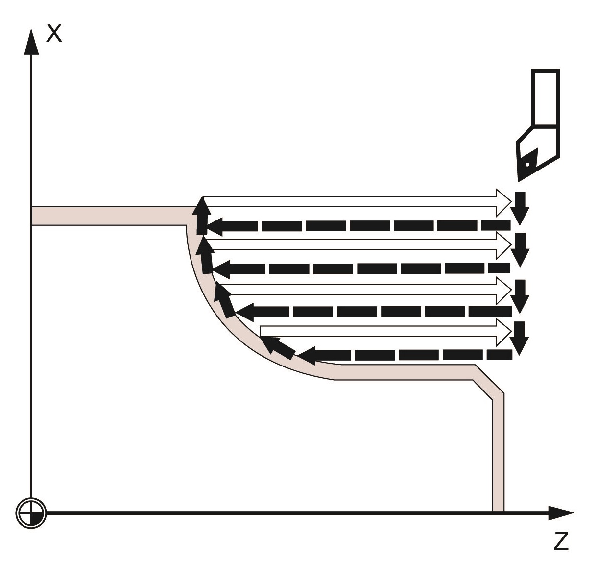
Fig.5.25 Roughing without relief cut elements
Roughing the relief cut elements:
1. Approach of the starting point for the next relief cut axis by axis with G00.
2. Infeed along the contour + finishing allowance with G01/G02/G03 and FF2.
3. Approach of paraxial roughing intersection point with G1 and at feedrate FF1
4. Rounding along the contour, retraction and return are carried out as with the first machining step
5. If there are further relief cut elements, this sequence is repeated for each relief cut.
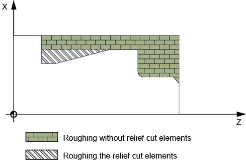
Fig.5.26 Roughing with the relief cut elements
Finishing:
1. The cycle starting point is approached axis by axis with G00
2. The contour starting point is approached with G00 in both axes at the same time
3. Finishing along the contour with G01/G02/G03 and FF3
4. Retraction to the starting point with both axes and G00
Explanation of parameters:
NSP (name)
This parameter is used to specify the contour name. The name of the contour subroutine is subject to all name conventions described in the Programming Manual.
IDEP (infeed depth)
The IDEP parameter is used to define the maximum possible infeed depth for the roughing process. The cycle will automatically calculate the current infeed depth used for roughing. With contours containing relief cut elements, the roughing process is divided by the cycle into individual roughing sections. The cycle calculates a new current infeed depth for each roughing section. This infeed depth is always between the programmed infeed depth and the half of its value. The number of required roughing steps is determined on the basis of the total depth of a roughing section and of the programmed maximum infeed depth to which the total depth to be machined is distributed equally. This provides optimum cutting conditions. For roughing this contour, the machining steps shown in the illustration result.
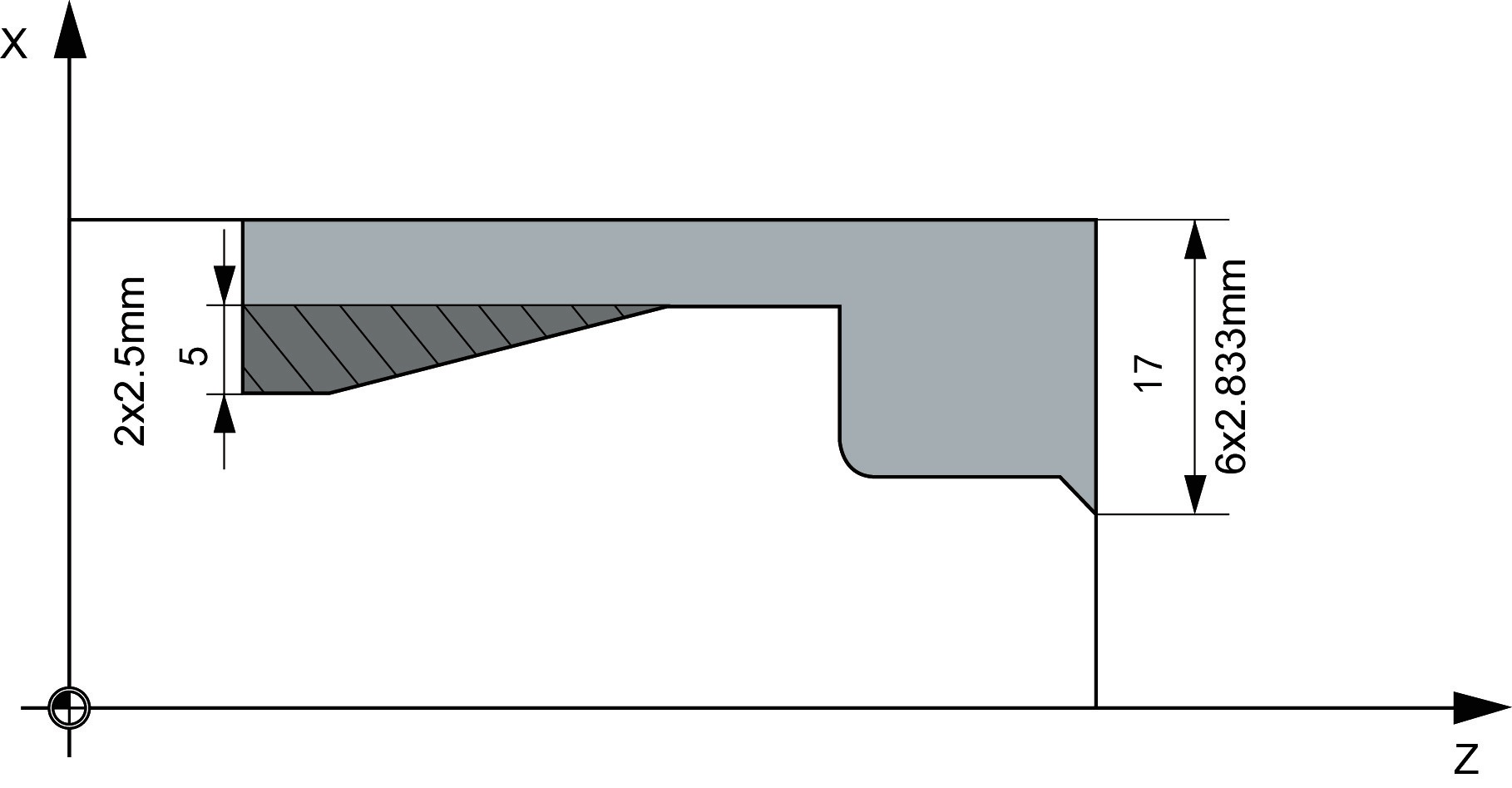
Fig.5.27 Roughing step and infeed depth
Example of calculating the current infeed depth:
Machining section 1 has a total depth of 17 mm. If the maximum infeed depth is 3 mm, six roughing cuts are required. These are carried out with an infeed of 2.833mm.
Machining section 2 has a total depth of 5mm. 2 roughing steps are carried out with an infeed of 2.5 mm each.
FAL, FALZ and FALX (finishing allowance)
A finishing allowance for roughing can be specified either using the parameters FALZ and FALX if you want to specify different finishing allowances axis-specifically or via the parameter FAL for a finishing allowance that follows the contour. In this case, this value is taken into account in both axes as a finishing allowance. No plausibility check is carried out for the programmed values. In other words: If all three parameters are assigned values, all these finishing allowances are taken into account by the cycle. Roughing is always carried out up to these finishing allowances. The resulting residual corner is also removed parallel to the contour after each paraxial roughing process immediately so that no additional residual corner cut is required after completion of roughing. If no finishing allowances are programmed, stock is removed when roughing up to the final contour.
FF1, FF2 and FF3 (feedrate)
It is possible to specify different feedrates for the individual machining steps, as shown in Fig.5.28.

Fig.5.28 The feedrate of each processing step
TYP (machining type):
Table5.1 Type of machining
|
Value |
Longitudinal/face (L/P) |
Ext. / int. (A/I) |
Roughing/finishing/complete |
|
1 |
L |
A |
Roughing |
|
2 |
P |
A |
Roughing |
|
3 |
L |
I |
Roughing |
|
4 |
P |
I |
Roughing |
|
5 |
L |
A |
Finishing |
|
6 |
P |
A |
Finishing |
|
7 |
L |
I |
Finishing |
|
8 |
P |
I |
Finishing |
|
9 |
L |
A |
Complete machining |
|
10 |
P |
A |
Complete machining |
|
11 |
L |
I |
Complete machining |
|
12 |
P |
I |
Complete machining |
In longitudinal machining, the infeed is always carried out along the transversal axis, and in face machining - along the longitudinal axis. External machining means that the infeed is carried out in the direction of the negative axis. With internal machining, the infeed is carried out in the direction of the positive axis. The TYP parameter is subjected to a plausibility check. If its value is not in the range 1 ... 12 when the cycle is called, the cycle is aborted with alarm.
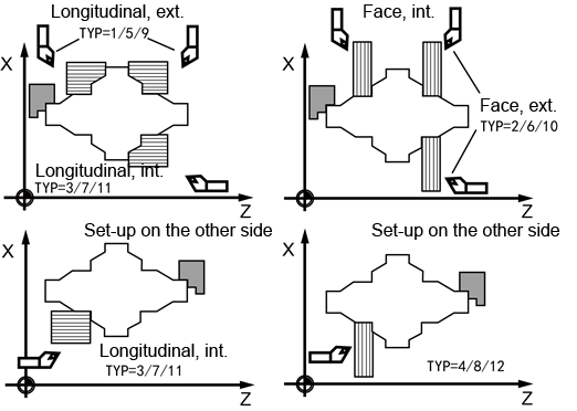
Fig.5.29 Machining type
DWT and DAM (dwell time and path length)
These parameters can be used to achieve an interruption of the individual roughing steps after certain distances traversed in order to carry out chip breaking. These parameters are only relevant for roughing. The parameter DAM is used to define the maximum distance after which chip breaking is to be carried out. In DWT, an appropriate dwell time (in seconds) can be programmed which is carried out at each of the cut interruption points. If no distance is specified for the cut interruption (DAM=0), uninterrupted roughing steps without dwell times are created.
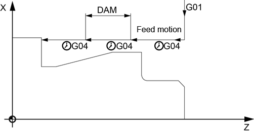
Fig.5.30 Dwell time and distance traveled
VRT (lift-off distance)
Parameter VRT can be used to program the amount by which the tool is retracted in both axes when roughing. For VRT=0 (parameter not programmed), the tool will retract by 1 mm. The VRT retraction path is used when roughing after each depth infeed.
More explanation:
Contour definition
1. The contour must contain at least 3 blocks with motions in the two axes of the machining plane. If the contour program is shorter, the cycle is aborted after the alarms have been output.
2. Only programming with G00, G01, G02, G03, G90/G91, G70/G71 and DIAMON/ DIAMOF are permitted as the geometry in the contour. Furthermore, it is also possible to program the commands for rounding and chamfer.
3. The first block with a traversing motion in the current machining plane must contain a motion command G00 or G01, and must program two coordinate values which can not be omitted
4. In the contour subroutine, the instructions G41/G42, G94/G95, G54~G59, G501 and G33 are not allowed.
5. In the subroutine, the instructions T, D, S, M, F, G04, G74/G75, G25/G26, G60/G64/G09, G17/G18/G19, G94/G95/G96/G97 are not allowed to program, otherwise alarm is generated.
6. In the contour subroutine, advanced instructions such as IF, GOTO, variables (including R parameters and array) definition and assignment can be used.
7. To machine the programmed contour, a cycle-internal memory is prepared which can accommodate a certain maximum number of contour elements; how many, depends on the contour. If a contour contains too many contour elements, the cycle is canceled, and alarm is issued. In this case, the contour must be split over several contour sections, and the cycle for each section must be called separately
8. If the maximum diameter is not at the programmed end or starting point of the contour, the cycle will automatically add an axis-parallel straight line to complete the contour maximum, and this part is removed as the undercut.
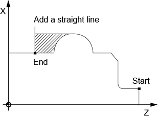
Fig.5.31 Contour definition
Contour direction
The direction in which the stock removal contour is programmed can be freely selected. In the cycle, the machining direction is defined automatically. In complete machining, the contour is finished in the same direction as machining was carried out when roughing. When deciding on the machining direction, the first and the last programmed contour points are taken into account. Therefore, both coordinates must always be programmed in the first block of the contour subroutine.
Starting point
The cycle determines the starting point for the machining operation automatically. The starting point is located in the axis in which the depth infeed is carried out, shifted from the contour by the amount of the finishing allowance + lift-off distance (parameter VRT). In the other axis, it is by finishing allowance + VRT ahead of the contour starting point. When the starting point is approached, the cutter radius compensation is selected internally in the cycle. The last point before the cycle is called must therefore be selected such that this approach is possible without collision and space enough is provided to carry out the appropriate compensatory motion.
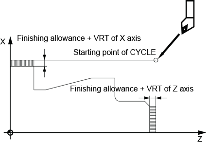
Fig.5.32 Starting point
Example:
Stock removal cycle
Machining type:
Longitudinal and external, complete machining. X axis finishing machining allowance is 0.5mm, Z axis finishing machining allowance is 0.3mm. Rough machine without interruption. Maximum infeed depth 3mm and contour subroutine name is "SUB95.
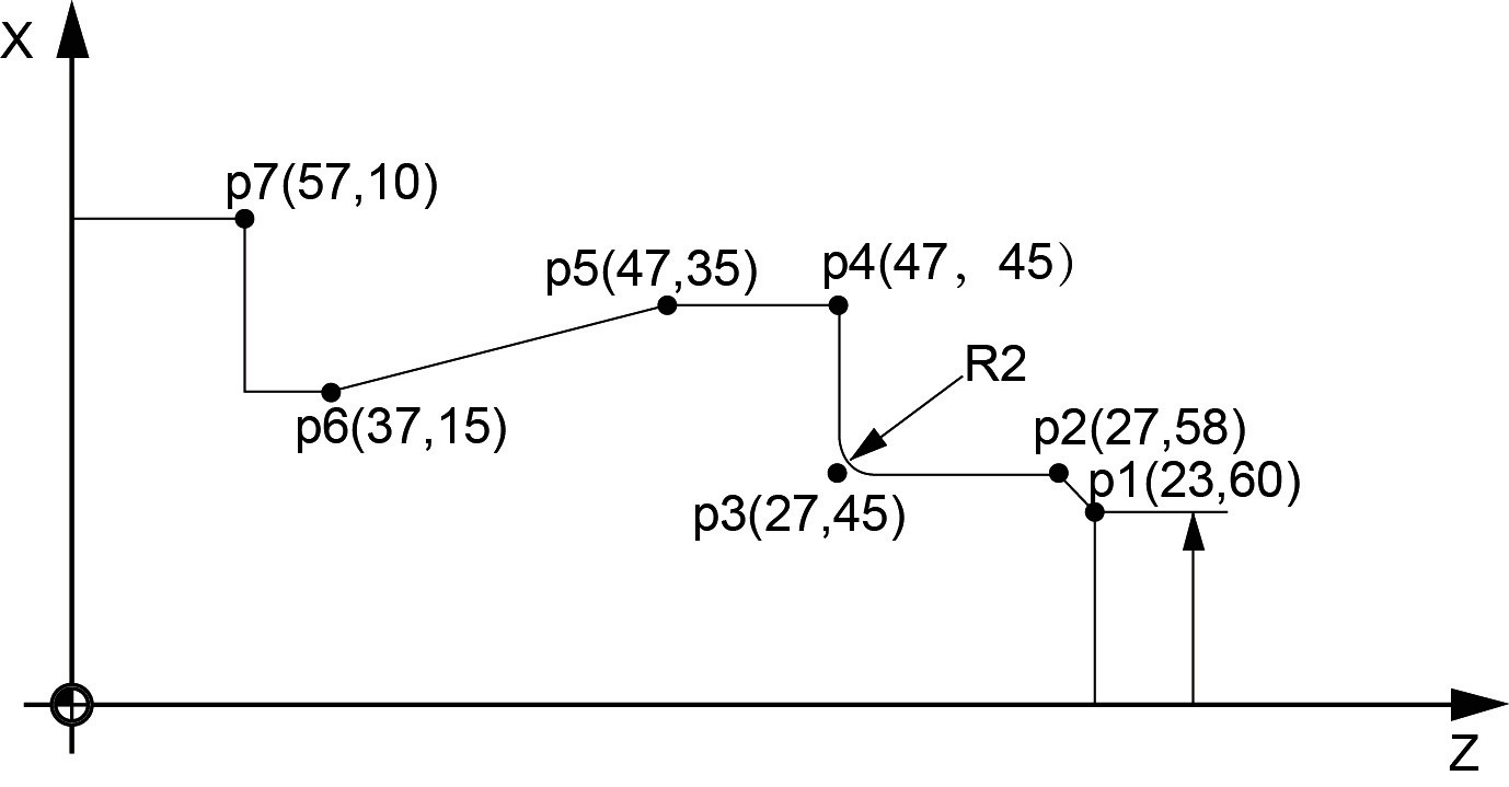
Fig.5.33 Example
The main program
|
N10 T1 D1 S500 M03 |
The definition of cutting parameters |
|
N20 G95 G90 F0.2 |
|
|
N30 G00 X62 Z62 |
approach starting position |
|
N40 CYCLE95(“SUB95”, 3, 0.3, 0.5, 0, 0.4, 0.4, 0, 1, 0, 0, 2) |
Cycle call |
|
N50 G90 G00 X62 Z62 |
Reapproach starting position |
|
N60 M02 |
End of program |
Contour subroutine “SUB95.iso”
|
N100 G00 X23 Z60 |
approach at the starting point of the contour |
|
N110 G01 X27 Z58 |
Traverse axis by axis |
|
N120 Z45 RND=2 |
Rounding with radius 2 |
|
N130 X47 |
|
|
N140 Z35 |
|
|
N150 X37 Z15 |
|
|
N160 Z10 |
|
|
N170 X57 |
|
|
N180 RET |
End of subroutine |
